background image

Operating Instructions

Modular Safety Control System MSC

158

(Translation of the original operating instructions) 2121331-04-04/19

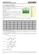
9.5.1.2.  Reset (RESET)

This operator generates a system reset if there is an OFF-ON-OFF 

transition with a duration of less than 5 s on the corresponding input.

t <  5 s 

IN  

Figure 192:  Reset duration

Figure 193:  Reset


¨

If the duration is > 5 s, there is no reset.


¨

Can be used to reset malfunctions without interrupting the supply to the system.

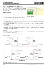
9.5.1.3.  Interpage In/Out

If the circuit diagram is very comprehensive and a connection between to elements that are a long way apart is necessary, 

the component "Interpage: In/Out" must be used.

Left part  
of the diagram

INTERPAGE OUT


INTERPAGE IN

Right part  
of the diagram

Figure 194:  Interpage: In/Out

To establish a connection, "Interpage: In" and "Interpage: Out" must have the same name.

Summary of Contents for MSC

Page 1: ...EN Operating Instructions Installation and use Modular Safety Control System MSC ...

Page 2: ...14 5 3 Electrical connections 14 5 3 1 Information in relation to connecting cables 15 5 3 1 1 Base unit MSC CB 15 5 3 2 USB connection 16 5 3 3 MSC configuration memory M A1 16 5 3 3 1 MULTIPLE LOAD function 16 5 3 3 2 RESTORE function 17 5 3 3 3 Module FI8FO2 17 5 3 3 4 Module FI8 18 5 3 3 5 Module FM4 18 5 3 3 6 Module FI16 19 5 3 3 7 Module AC FO4 20 5 3 3 8 Module AC FO2 20 5 3 3 9 Modules SP...

Page 3: ...1 Base unit MSC CB Figure 14 40 8 3 2 Module FI8FO2 Figure 15 41 8 3 3 Module FI8 Figure 16 42 8 3 4 Module FM4 Figure 17 43 8 3 5 Module FI16 Figure 18 44 8 3 6 Module AC FO2 Figure 19 45 8 3 7 Module AC FO4 Figure 20 46 8 3 8 Module AZ FO4 Figure 21 47 8 3 9 Module AZ FO4F08 Figure 22 48 8 3 10 Module O8 Figure 23 49 8 3 11 Module O16 Figure 24 50 8 3 12 Modules SPM0 SPM1 SPM2 Figure 25 51 8 3 1...

Page 4: ...hecking the system 80 9 2 Item specific function blocks 81 9 2 1 Output items 81 9 2 1 1 Safety outputs OSSD 81 9 2 1 2 Safety output SINGLE_OSSD 82 9 2 1 3 Signal output STATUS 84 9 2 1 4 Fieldbus sensor FIELDBUS PROBE 85 9 2 1 5 Relay RELAY 85 9 2 1 6 Usage of the automatic start A or manual start B category 2 87 9 2 2 Input items 89 9 2 2 1 Emergency stop E STOP 89 9 2 2 2 Interlock INTERLOCK 9...

Page 5: ... RESTART operators 133 9 4 2 7 Macro monitored restart MACRO RESTART MONITORED max number 16 including other RESTART operators 134 9 4 3 Guard lock logic GUARD LOCK max number 4 135 9 4 3 1 GUARD LOCK 135 9 4 4 COUNTER operators 137 9 4 4 1 Counter COUNTER max number 16 137 9 4 5 TIMER operators max number 32 139 9 4 5 1 MONOSTABLE 139 9 4 5 2 MONOSTABLE_B 140 9 4 5 3 Passing make contact PASSING ...

Page 6: ...Modular Safety Control System MSC 6 Translation of the original operating instructions 2121331 04 04 19 10 Ordering information and accessories 170 11 Inspection and service 170 12 Service 170 13 Declaration of conformity 170 ...

Page 7: ...njuries Caution slight injuries possible NOTICE Important Notice about possible device damage Important information Tip Tip useful information 1 4 Supplementary documents The overall documentation for this device consists of the following documents Document title document number Contents Operating Instructions Safety Relays and Control Systems MSC 2121331 This document I n t e r n e t www Possibly...

Page 8: ...Ì Ì The programming configuration of the MSC system is the sole responsibility of the installer or the user Ì Ì This programming configuration must correspond to the application specific risk analysis and all applicable standards Ì Ì After programming configuration and installation of the MSC system and all related devices a complete application safety check must be undertaken see section Checking...

Page 9: ...sponds to the following standards EN IEC 61131 2 Programmable controllers Part 2 Equipment requirements and tests EN ISO 13489 1 Safety of machinery Safety related parts of control systems General principles for design EN IEC 61496 1 Safety of machinery Electro sensitive protective equipment Part 1 General requirements and tests EN IEC 61508 1 Functional safety of electrical electronic programmabl...

Page 10: ...puts The greater the number of AZ FO4 AZ FO4O8 modules used the fewer dual channel outputs are available The communication between the base unit MASTER and the extension modules SLAVES is via the MSCB 5 way bus pro prietary bus from EUCHNER on the rear side of every module In addition 8 inputs and 16 outputs are available and can be controlled using sensors via the fieldbus The number of inputs in...

Page 11: ...op in put Only the modules AZ FO4O8 AH FO4SO8 and O8 have 8 programmable signal outputs and the module O16 has 16 programmable signal outputs Using the software EUCHNER Safety Designer complex logic can be configured using logical operators and safety functions such as muting timers counters etc defined All this is achieved using a straightforward intuitive graphic user interface The configuration...

Page 12: ...d other product literature Ì Ì Multilingual installation instructions Important Ì Ì The MSCB plug connector on the rear and the M A1 memory card can be ordered separately The scope of delivery of the extension modules includes Ì Ì Multilingual installation instructions Ì Ì Rear MSCB plug connector Important Ì Ì The MSCB plug connector supplied and a further MSCB plug connector for the connection t...

Page 13: ...les to be installed 2 Fasten the row of plug connectors assembled in this manner to the DIN rail first hook on at the top 3 Fasten modules to the rail and during this process place the contacts on the base of the module over the related plug connector Carefully push in module until it noticeably engages 4 To remove the module the catch on the rear of the module must be pulled down with the aid a s...

Page 14: ...from when the stop signal is sent A procedure is described that permits system planners to determine the minimum safety distance between protective equipment in particular ESPE e g light grids safety mats or pressure sensitive floors and two hand controls and a specific danger zone It contains a rule for the arrangement of protective equipment based on the approach speed and time taken by the mach...

Page 15: ...utput Safety output 1 PNP active high 6 OSSD1_B Output PNP active high 7 RESTART_FBK1 Input Feedback loop restart 1 Input as per EN 61131 2 8 OUT_STATUS1 Output Programmable digital output PNP active high 9 OSSD2_A Output Safety output 2 PNP active high 10 OSSD2_B Output PNP active high 11 RESTART_FBK2 Input Feedback loop restart 2 Input as per EN 61131 2 12 OUT_STATUS2 Output Programmable digital...

Page 16: ...rs Every new project transferred from the PC to the MSC CB is written to the memory card M A1 Always switch off MSC CB before logging onto or logging off from the M A1 Insert card in the slot on the rear of the MSC CB direction as shown in Figure 4 M A1 M A1 label Label with technical data Figure 4 M A1 5 3 3 1 MULTIPLE LOAD function To configure several MSC CB modules without using a PC and the U...

Page 17: ... supply 24 VDC 2 NODE_SEL0 Input Node selection Input type B as per EN 61131 2 3 NODE_SEL1 Input Input type B as per EN 61131 2 4 GND Power supply 0 VDC 5 OSSD1_A Output Safety output 1 PNP active high 6 OSSD1_B Output PNP active high 7 RESTART_FBK1 Input Feedback loop restart 1 Input as per EN 61131 2 8 OUT_STATUS1 Output Programmable digital output PNP active high 9 OSSD2_A Output Safety output ...

Page 18: ...ODE_SEL0 Input Node selection Input type B as per EN 61131 2 3 NODE_SEL1 Input Input type B as per EN 61131 2 4 GND Power supply 0 VDC 5 INPUT1 Input Digital input 1 Input as per EN 61131 2 6 INPUT2 Input Digital input 2 Input as per EN 61131 2 7 INPUT3 Input Digital input 3 Input as per EN 61131 2 8 INPUT4 Input Digital input 4 Input as per EN 61131 2 9 OUT_TEST1 Output Output for short circuit d...

Page 19: ... circuit detection PNP active high 11 OUT_TEST3 Output Output for short circuit detection PNP active high 12 OUT_TEST4 Output Output for short circuit detection PNP active high 13 INPUT5 Input Digital input 5 Input as per EN 61131 2 14 INPUT6 Input Digital input 6 Input as per EN 61131 2 15 INPUT7 Input Digital input 7 Input as per EN 61131 2 16 INPUT8 Input Digital input 8 Input as per EN 61131 2...

Page 20: ... restart 4 Input as per EN 61131 2 20 OUT_STATUS4 Output Programmable digital output PNP active high 21 OSSD3_A Output Safety output 3 PNP active high 22 OSSD3_B Output PNP active high 23 RESTART_FBK3 Input Feedback loop restart 3 Input as per EN 61131 2 24 OUT_STATUS3 Output Programmable digital output PNP active high Table 7 Module AC FO4 5 3 3 8 Module AC FO2 TERMINAL SIGNAL TYPE DESCRIPTION VE...

Page 21: ... VDC on PROXI1 7 PROXI1 IN1 3 WIRES Input PROXI1 NO contact 8 PROXI1 IN2 4 WIRES Input PROXI1 NC contact 9 PROXI2_24 V Output Connections for the 2nd proximity switch see Page 29 Power supply 24 VDC on PROXI2 10 PROXI2_REF Output Power supply 24 VDC on PROXI2 11 PROXI2 IN1 3 WIRES Input PROXI2 NO contact 12 PROXI2 IN2 4 WIRES Input PROXI2 NC contact 13 n c Not connected 14 n c 15 n c 16 n c Table ...

Page 22: ...4VDC 5VDC 24VDC ENCODER HTL MODULE RJ45 CONNECTOR ENCODER SIN COS M ODULE RJ45 CONNECTOR PINK GREY GREEN YELLOW WHITE BROWN 7 N C 8 N C PINK GREY GREEN YELLOW WHITE BROWN 7 N C 8 N C N C N C N C N C 5VDC ENCODER HTL EXT_0V EXT_0V EXT_0V EXT_0V 5 B B 6 A A 4 3 7 8 B B 6 5 A A 4 3 1 2 2 1 POWER SUPPLY EXT_0V 24VDC 5VDC 24VDC ENCODER TTLB MODULE RJ45 CONNECTOR PINK GREY GREEN YELLOW WHITE BROWN 7 N C...

Page 23: ...nput Node selection Input type B as per EN 61131 2 3 NODE_SEL1 Input Input type B as per EN 61131 2 4 GND Power supply 0 VDC 5 REST_FBK1 Input Feedback loop restart 1 Input as per EN 61131 2 6 REST_FBK2 Input Feedback loop restart 2 Input as per EN 61131 2 7 REST_FBK3 Input Feedback loop restart 3 Input as per EN 61131 2 8 REST_FBK4 Input Feedback loop restart 4 Input as per EN 61131 2 9 A_NO1 Out...

Page 24: ...SEL1 Input Input type B as per EN 61131 2 4 GND Power supply 0 VDC 5 24 VDC STATUS 1 8 Power supply 24 VDC programmable digital output 1 8 6 24 VDC STATUS 9 16 Power supply 24 VDC programmable digital output 9 16 7 8 9 SYS_STATUS1 Output Programmable digital output 1 PNP active high 10 SYS_STATUS2 Output Programmable digital output 2 PNP active high 11 SYS_STATUS3 Output Programmable digital outpu...

Page 25: ...channel or 2 dual channel 10 OSSD2 Output Safety output 2 11 OSSD3 Output Safety output 3 12 OSSD4 Output Safety output 4 13 14 24 VDC Power supply 24 VDC 15 16 17 SYS_STATUS1 Output Programmable digital output 1 PNP active high 18 SYS_STATUS2 Output Programmable digital output 2 PNP active high 19 SYS_STATUS3 Output Programmable digital output 3 PNP active high 20 SYS_STATUS4 Output Programmable ...

Page 26: ...rtake complete system CHECK see CHECKING the system 2 Check whether all cables are inserted correctly and the terminal blocks are tightened properly 3 Check whether all LEDs indicators illuminate correctly 4 Check whether all sensors connected to the MSC system are positioned correctly 5 Check whether the MSC system is properly fastened to the DIN rail 6 Check whether all external indicators lamps...

Page 27: ...ounting Validation software OK Preparation of the diagram NO Electrical connections between the MSC modules and external sensors YES Download the diagram to MSC CB NO YES Disconnect the connection via USB Configuration check incl complete system CHECK see Project validation on MSC CB OK Switch on the system Connection via USB to MSC CB Figure 7 Flow chart ...

Page 28: ... can be simply set to logic level 0 0 VDC 7 1 2 NODE_SEL The inputs NODE_SEL0 and NODE_SEL1 on the extension modules are used to assign an address to the extension modules using the connections given in Table 16 NODE_SEL1 TERMINAL 3 NODE_SEL0 TERMINAL 2 NODE 0 0 or not connected 0 or not connected NODE 1 0 or not connected 24 VDC NODE 2 24 VDC 0 or not connected NODE 3 24 VDC 24 VDC Table 16 Node ...

Page 29: ...on one axis The Performance Level PL e can be achieved under the following conditions The proximity switches must be mounted such that the signals produced overlap The proximity switches must be mounted such that at least one proximity switch is always actuated active Figure 8 Proximity switches Additional information Proximity switches with a PNP output must be used Proximity switches with a norm...

Page 30: ...tactors must be checked using an additional device Ì Ì The command switch for starting RESTART must be installed outside the danger zone in a place from which there is a clear view of the danger area and the entire working area affected Ì Ì It must not be possible to actuate the command switch from inside the danger zone Each OSSD pair has a corresponding RESTART_FBK input OPERATING MODE EDM RESTA...

Page 31: ...using the OUT_TEST signals Figure 9 MSC CB E STOP INTERLOCK The maximum number of inputs that can be controlled by each OUT_TEST output 4 INPUTS parallel connection MSC CB FI8FO2 FI8 FM4 FI16 The maximum permissible length of the cable on the OUT_TEST output is 100 m Figure 9 OUT_TEST 7 2 3 OSSD MSC CB FI8FO2 The OSSD outputs Output Signal Switching Device are short circuit proof monitored for cro...

Page 32: ...nt is foreseen in the configuration undertaken in the software EUCHNER Safety Designer Each OSSD output can be configured as shown in Table 18 Automatic The output is only activated as per the configuration defined by the software EUCHNER Safety Designer if 24 VDC are applied to the related input RESTART_FBK Manual The output is only activated as per the configuration defined by the software EUCHN...

Page 33: ... Ì Ì 4 single channel outputs 1 safety output per channel with corresponding RESTART_FBK input Ì Ì 2 dual channel outputs 2 safety outputs per channel with corresponding RESTART_FBK input MSC CE AH FO4SO8 MSC CE AH FO4SO8 Figure 11 Configuration of 2 channel double outputs safety category 4 Figure 12 Configuration of 4 channel single outputs safety category 4 On the use of the module AH FO4SO8 wit...

Page 34: ... modes for the modules AZ FO4 AZ FO4O8 that can be configured using the software EUCHNER SAFETY DESIGNER in the section Relay RELAY Excitation voltage 17 31 VDC Switching voltage min 10 VDC Switching current min 20 mA Switching voltage max DC 250 VDC Switching voltage max AC 400 VAC Switching current max 6 A Response time 12 ms Mechanical life contacts 20 x 106 Table 19 Technical data AZ FO4 AZ FO...

Page 35: ...ner see project report Fault reaction time ms The fault reaction time corresponds to the reaction time except on SPM modules with an encoder proximity switch interface In this case the fault reaction time is 2 s Base unit 10 6 12 6 TInput_filter MSC CB 1 extension module 11 8 26 5 TInput_filter MSC CB 2 extension modules 12 8 28 7 TInput_filter MSC CB 3 extension modules 13 9 30 8 TInput_filter MS...

Page 36: ...SB 2 0 Hi Speed cable length max 3 m Connection to extension module Via proprietary 5 way MSCB from EUCHNER 8 1 5 Module FI8FO2 PFHD EN IEC 61508 2010 5 72 E 9 Operating voltage 24 VDC 20 Power dissipation 3 W max Digital INPUTS no description 8 PNP active high as per EN 61131 2 Test OUTPUT no description 8 for checking for short circuits overload states Digital OUTPUTS no description 2 programmab...

Page 37: ...ule AH FO4SO8 PFHD IEC 61508 2010 9 28 E 09 Operating voltage 24 VDC 20 Power dissipation 4 W max Current OSSD outputs Max 2 A per channel Number of safety outputs OSSD 2 pairs or 4 single static safety outputs PNP active high 400 mA at 24 VDC max cat 4 INPUT_FBK RESTART no description 4 EDM control automatic or manual operation possible using RESTART button Digital OUTPUTS no description 8 progra...

Page 38: ...n terminals Configurable limit ranges 1 Hz 4 kHz Number of proximity switches max 2 Frequency max proximity switch 5 kHz Max number of axes 2 Frequency spacing standstill overspeed 10 Hz Spacing thresholds 5 Connection to MSC CB Via proprietary 5 way bus MSCB from EUCHNER 8 1 11 Modules AZ FO4 AZ FO4O8 Module AZ FO4 AZ FO4O8 PFHD EC IEC 61508 2010 2 9 E 9 2 94 E 9 Operating voltage 24 VDC 20 Power...

Page 39: ...1331 04 04 19 Translation of the original operating instructions Operating Instructions Modular Safety Control System MSC EN 8 2 Mechanical dimensions 114 5 mm 108 mm 22 5 mm 99 mm Figure 13 Module dimensions ...

Page 40: ...System layout OFF OFF OFF Flashes quickly OFF OFF Red OFF OFF SWSD is requesting connec tion extension module missing or not ready see System layout Flashes quickly OFF OFF Flashes quickly OFF OFF Red OFF OFF SWSD connected MSC CB stopped OFF OFF OFF ON OFF OFF Red OFF OFF Table 20 Indication on starting MEANING LED RUN GREEN IN FAIL RED EXT FAIL RED COM ORANGE IN1 8 YELLOW ENA BLUE OSSD1 2 RED GR...

Page 41: ...AIL RED IN1 8 YELLOW SEL ORANGE OSSD1 2 RED GREEN CLEAR1 2 YELLOW STATUS1 2 YELLOW NORMAL OPERATION OFF If the module is waiting for the first message from the base unit FLASHING If no INPUT or OUTPUT is requested by the configuration ON If INPUT or OUTPUT is requested by the configuration OFF OFF OUTPUT state Indicates the signal table NODE_SEL0 1 RED If output OFF GREEN If output ON ON Waiting f...

Page 42: ...ing MEANING LED RUN GREEN IN FAIL RED EXT FAIL RED SEL ORANGE IN1 8 YELLOW NORMAL OPERATION OFF If the module is waiting for the first message from the base unit FLASHING If no INPUT or OUTPUT is requested by the configuration ON If INPUT or OUTPUT is requested by the configuration OFF OFF Indicates the signal table NODE_SEL0 1 OUTPUT state ON Erroneous external connec tion detected Only the numbe...

Page 43: ...rting MEANING LED RUN GREEN IN FAIL RED EXT FAIL RED SEL ORANGE IN1 12 YELLOW NORMAL OPERATION OFF If the module is waiting for the first message from the base unit FLASHING If no INPUT or OUTPUT is requested by the configuration ON If INPUT or OUTPUT is requested by the configuration OFF OFF Indicates the signal table NODE_SEL0 1 INPUT state ON Erroneous external con nection detected Only the num...

Page 44: ...ing MEANING LED RUN GREEN IN FAIL RED EXT FAIL RED SEL ORANGE IN1 16 YELLOW NORMAL OPERATION OFF If the module is waiting for the first message from the base unit FLASHING If no INPUT or OUTPUT is requested by the configuration ON If INPUT or OUTPUT is requested by the configuration OFF OFF Indicates the signal table NODE_SEL0 1 INPUT state ON Erroneous external connec tion detected Only the numbe...

Page 45: ...tarting MEANING LED RUN GREEN IN FAIL RED EXT FAIL RED SEL ORANGE OSSD1 2 RED GREEN CLEAR1 2 YELLOW STATUS1 2 YELLOW NORMAL OPERATION OFF If the module is waiting for the first message from the base unit FLASHING If no INPUT or OUTPUT is requested by the configuration ON If INPUT or OUTPUT is requested by the configuration OFF Operation OK OFF Operation OK Indicates the signal table NODE_SEL0 1 RE...

Page 46: ...rting MEANING LED RUN GREEN IN FAIL RED EXT FAIL RED SEL ORANGE OSSD1 4 RED GREEN CLEAR1 4 YELLOW STATUS1 4 YELLOW NORMAL OPERATION OFF If the module is waiting for the first message from the base unit FLASHING If no INPUT or OUTPUT is requested by the configuration ON If INPUT or OUTPUT is requested by the configuration OFF Operation OK OFF Operation OK Indicates the signal table NODE_SEL0 1 RED ...

Page 47: ...ANING LED RUN GREEN IN FAIL RED EXT FAIL RED SEL0 1 ORANGE RELAY1 4 RED GREEN CLEAR1 4 YELLOW NORMAL OPERATION OFF If the module is waiting for the first message from the base unit FLASHING If no INPUT or OUTPUT is requested by the configuration ON If INPUT or OUTPUT is requested by the configuration OFF Operation OK OFF Operation OK Indicates the signal table NODE_SEL0 1 RED If contact open ON Wa...

Page 48: ...LED RUN GREEN IN FAIL RED EXT FAIL RED SEL0 1 ORANGE RELAY1 4 RED GREEN CLEAR1 4 YELLOW STATUS1 8 YELLOW NORMAL OPERATION OFF If the module is waiting for the first message from the base unit FLASHING If no INPUT or OUTPUT is requested by the configuration ON If INPUT or OUTPUT is requested by the configuration OFF Operation OK OFF Operation OK Indicates the signal table NODE_SEL0 1 RED If contact...

Page 49: ... ON ON ON ON ON Table 38 Indication on starting MEANING LED RUN GREEN IN FAIL RED EXT FAIL RED SEL0 1 ORANGE STATUS1 8 YELLOW NORMAL OPERATION OFF If the module is waiting for the first message from the base unit FLASHING If no INPUT or OUTPUT is requested by the configuration ON If INPUT or OUTPUT is requested by the configuration OFF Operation OK OFF Operation OK Indicates the signal table NODE_...

Page 50: ...ON ON ON ON ON Table 40 Indication on starting MEANING LED RUN GREEN IN FAIL RED EXT FAIL RED SEL0 1 ORANGE STATUS1 16 YELLOW NORMAL OPERATION OFF If the module is waiting for the first message from the base unit FLASHING If no INPUT or OUTPUT is requested by the configuration ON If INPUT or OUTPUT is requested by the configuration OFF Operation OK OFF Operation OK Indicates the signal table NODE_...

Page 51: ...T FAIL RED SEL ORANGE ENC YELLOW PROX YELLOW SH YELLOW NORMAL OPERATION OFF If the module is waiting for the first message from the base unit FLASHING If no INPUT or OUTPUT is requested by the configuration ON If INPUT or OUTPUT is requested by the configuration OFF Operation OK OFF Operation OK Indicates the signal table NODE_SEL0 1 ON Encoder connected and operational ON Proximity switch connect...

Page 52: ...AIL RED EXT FAIL RED SEL0 1 ORANGE RELAY1 4 RED GREEN CLEAR1 4 YELLOW STATUS1 8 YELLOW NORMAL OPERATION OFF If the module is waiting for the first message from the base unit FLASHING If no INPUT or OUTPUT is requested by the configuration ON If INPUT or OUTPUT is requested by the configuration OFF Operation OK OFF Operation OK Indicates the signal table NODE_SEL0 1 RED If output is OFF ON Waiting ...

Page 53: ...t error OFF Flashes 4 times OFF OFF OFF OFF Flashes 4 times only the LED corresponding to the output in the error mode OFF OFF Ì Ì Check OSSD1 2 connections Ì Ì If the problem persists send MSC CB to EUCHNER for repair Error during communication with extension module OFF Flashes 5 times OFF OFF OFF OFF OFF OFF OFF Ì Ì Restart system Ì Ì If the problem persists send MSC CB to EUCHNER for repair Err...

Page 54: ... error OFF Flashes 4 times OFF OFF Flashes 4 times only the LED corresponding to the output in the error mode OFF OFF Ì Ì Check OSSD1 2 connections Ì Ì If the problem persists send FI8FO2 to EUCHNER for repair Error during communi cation with base unit OFF Flashes 5 times OFF OFF OFF OFF OFF Ì Ì Restart system Ì Ì If the problem persists send FI8FO2 to EUCHNER for repair Error in another extension...

Page 55: ...ware upgrade OSSD output error OFF Flashes 4 times OFF OFF Ì Ì Restart system Ì Ì If the problem persists send FI8 to EUCHNER for repair Error during communi cation with base unit OFF Flashes 5 times OFF OFF Ì Ì Restart system Ì Ì If the problem persists send FI8 to EUCHNER for repair Error in another exten sion module or MSC CB OFF ON OFF OFF Ì Ì Restart system Ì Ì Check which module is in the ER...

Page 56: ...re upgrade OSSD output error OFF Flashes 4 times OFF OFF Ì Ì Restart system Ì Ì If the problem persists send FM4 to EUCH NER for repair Error during communi cation with base unit OFF Flashes 5 times OFF OFF Ì Ì Restart system Ì Ì If the problem persists send FM4 to EUCH NER for repair Error in another exten sion module or MSC CB OFF ON OFF OFF Ì Ì Restart system Ì Ì Check which module is in the ER...

Page 57: ...re version not compatible with MSC CB Send to EUCHNER for firmware upgrade Error during communi cation with base unit OFF Flashes 5 times OFF OFF Ì Ì Restart system Ì Ì If the problem persists send FI16 to EUCHNER for repair Error in another exten sion module or MSC CB OFF ON OFF OFF Ì Ì Restart system Ì Ì Check which module is in the ERROR mode Extension module of the same type with the same addr...

Page 58: ...nnections Ì Ì If the problem persists send AC FO2 AC FO4 to EUCHNER for repair Error during communica tion with base unit OFF Flashes 5 times OFF OFF OFF OFF Ì Ì Restart system Ì Ì If the problem persists send AC FO2 AC FO4 to EUCHNER for repair Error in another extension module or MSC CB OFF ON OFF OFF OFF OFF Ì Ì Restart system Ì Ì Check which module is in the ERROR mode Extension module of the ...

Page 59: ... output in the ERROR mode OFF Ì Ì If the problem persists send module to EUCHNER for repair Error during communica tion with base unit OFF Flashes 5 times OFF OFF OFF Ì Ì Restart system Ì Ì If the problem persists send module to EUCHNER for repair Error in another extension module or MSC CB OFF ON OFF OFF OFF Ì Ì Restart system Ì Ì Check which module is in the ERROR mode Extension module of the sa...

Page 60: ...persists send module to EUCHNER for repair Error during commu nication with base unit OFF Flashes 5 times OFF OFF OFF OFF Ì Ì Restart system Ì Ì If the problem persists send module to EUCHNER for repair Error in another extension module or MSC CB OFF ON OFF OFF OFF OFF Ì Ì Restart system Ì Ì Check which module is in the ERROR mode Extension module of the same type with the same address detected OF...

Page 61: ... base unit OFF Flashes 5 times OFF OFF Ì Ì Restart system Ì Ì If the problem persists send module to EUCHNER for repair Error in another exten sion module or MSC CB OFF ON OFF OFF Ì Ì Restart system Ì Ì Check which module is in the ERROR mode Extension module of the same type with the same address detected OFF Flashes 5 times Flashes 5 times OFF Ì Ì Change address of the module see section NODE_SE...

Page 62: ...NER for repair Error in another exten sion module or MSC CB OFF ON OFF OFF OFF Ì Ì Restart system Ì Ì Check which module is in the ERROR mode Extension module of the same type with the same address detected OFF Flashes 5 times Flashes 5 times OFF OFF Ì Ì Change address of the module see section NODE_SEL Internal node detection error OFF Flashes 3 times OFF Flashes 3 times OFF OFF Ì Ì Send to EUCHN...

Page 63: ...ty switch error OFF Flashes 3 times OFF Flashes 3 times Ì Ì Replace proximity switch Ì Ì Send to EUCHNER for repair Internal node detec tion error OFF Flashes 3 times OFF Flashes 3 times OFF OFF OFF Ì Ì Send module to EUCHNER for repair Extension module of the same type with the same address detected OFF Flashes 5 times Flashes 5 times OFF OFF OFF Ì Ì Change address of the mod ule see section NODE...

Page 64: ...muni cation with base unit OFF Flashes 5 times OFF OFF OFF OFF Ì Ì Restart system Ì Ì If the problem persists send module to EUCHNER for repair Error in another extension module or MSC CB OFF ON OFF OFF OFF OFF Ì Ì Restart system Ì Ì Check which module is in the ERROR mode Extension module of the same type with the same address detected OFF Flashes 5 times Flashes 5 times OFF OFF OFF Ì Ì Change ad...

Page 65: ...an be defined They are described in the following 9 1 Installing the software 9 1 1 PC hardware requirements Ì Ì RAM 256 MB adequate for running Windows XP SP3 Framework 4 0 Ì Ì Hard disk 500 MB free storage capacity Ì Ì USB port 1 1 2 0 or 3 0 Ì Ì CD ROM drive 9 1 2 PC software requirements Windows XP with Service Pack 3 installed or higher Microsoft Framework 4 0 or higher must be installed on t...

Page 66: ...start screen is displayed Figure 39 EUCHNER Safety Designer You can now start to create projects 9 1 5 Default toolbar The default toolbar is shown in Figure 40 The significance of the buttons is given in the following Figure 40 EUCHNER Safety Designer default toolbar 1 CREATE NEW PROJECT 2 CHANGE CONFIGURATION composition of different modules 3 CHANGE USER PARAMETERS name company etc 4 SAVE ACTUA...

Page 67: ... MSC 15 DISCONNECT FROM MSC 16 DOWNLOAD EXISTING PROJECT from MSC 17 MONITOR I O REALTIME STATUS GRAPHIC 18 MONITOR I O REALTIME STATUS TEXT 19 DOWNLOAD LOG FILE 20 DISPLAY SYSTEM CONFIGURATION 21 DOWNLOAD FAULT MEMORY 22 CLEAR FAULT MEMORY 23 SCHEMATIC SIMULATION 24 GRAPHIC SIMULATION 25 CHANGE PASSWORD 26 ONLINE HELP 27 RESTORE PASSWORD Figure 41 EUCHNER Safety Designer default buttons 9 1 6 Men...

Page 68: ...UCHNER Safety Designer Project information Then a window appears in EUCHNER Safety Designer in which only the module MSC CB is shown You can add the modules necessary for the system using the list boxes at the top of the screen Select extension module The node can be selected using the list box at the bottom of the screen SELECT EXTENSION MODULE to add to the configuration SELECT NODE from 0 to 3 ...

Page 69: ...roject information appears Figure 43 It is not necessary to log off from ESWD for this action As a rule this feature is used when a new user needs to prepare a new project also on the usage of a project prepared previously 9 1 8 Tool windows for ITEMS OPERATOR CONFIGURATION Four large tool windows are displayed on the left and right side of the main window Figure 45 1 2 3 4 Figure 45 EUCHNER Safet...

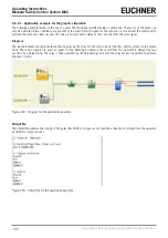
Page 70: ... in the fol lowing and drag to the design workspace Ì Ì After the selection of an item the PROPERTY window is activated where you must complete the fields as necessary Ì Ì You can set a specific numeric value on a slider e g Filter using the left and right arrow keys on the keyboard or by clicking the ends of the slider Ì Ì Items can be linked together by selecting the required pin using the mouse...

Page 71: ...ow Status block activate deactivate the logical negation on the input pin Ì Ì On operator blocks Copy paste Delete Alignment with other function blocks with multiple selection Help Activate deactivate the logical negation Monitor mode show hide the property window Ì Ì On terminals Alignment with other function blocks with multiple selection Ì Ì On connections wires Delete Indication of the entire ...

Page 72: ... are highlighted in yellow on the left The MSC outputs from 1 to 4 are activated as per the conditions that are specified in the interlock INTERLOCK and emergency stop E STOP see page 81 Emergency stop E STOP and page 83 Interlock INTERLOCK Click a block to select it and activate the PROPERTY window on the right where you can configure the activation and test parameters for the block Figure 48 EUC...

Page 73: ...ct validation If the validation is successful a sequential number is assigned to the INPUT and OUTPUT on the diagram This number then appears also in the REPORT and in the monitor in EUCHNER Safety Designer The configuration can only be transferred after successful validation WARNING The validation function only checks whether the programming is appropriate for the properties of the MSC system How...

Page 74: ...ort WARNING Ì Ì This definition of the PL and the other related parameters as per EN ISO 13849 1 relate only to the functions that have been implemented by EUCHNER Safety Designer in the MSC system here it is assumed that the configuration has been undertaken correctly Ì Ì The data for all devices connected to the MSCB in the application must be taken into account in the actual PL for the entire a...

Page 75: ...ct 9 1 10 5 Downloading a configuration file project from MSC CB Click the button on the default toolbar to download a project from the base unit MSC CB to the configuration software EUCHNER Safety Designer EUCHNER Safety Designer displays the project saved in the MSC CB password required level 1 NOTICE Ì Ì If the project is to be used for other modules of type MSC CB the components connected in e...

Page 76: ... modules Figure 53 Overview of system layout If there is an error in one of the modules detected the following window appears In the example below the node number of module FI8 is not correct indicated by red text Figure 54 Erroneous system layout 9 1 10 8 Disconnecting the system Click the button to disconnect the PC from the MSC CB After the disconnection of the system then system is reset and r...

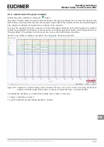
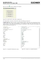
Page 77: ...tivate the monitor password required level 1 A pop up window with the following content appears in real time Ì Ì Status of the inputs if the item has two or more input connections to MSC only the first is indicated in the monitor as active see example shown Ì Ì Input diagnostics Ì Ì OSSD state Ì Ì OSSD diagnostics Ì Ì Status of the digital outputs Ì Ì OUT_TEST diagnostics Figure 55 Monitor text fo...

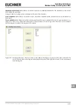
Page 78: ...e diagnostics can be read in real time as follows Ì Ì RED OFF Ì Ì GREEN ON Ì Ì DOTTED ORANGE Connection error Ì Ì DOTTED RED ENABLE present e g RESTART SPECIAL CASES NETWORK OPERATOR NETWORK IN and NETWORK OUT signals Ì Ì THICK CONTINUOUS RED LINE STOP Ì Ì THICK CONTINUOUS GREEN LINE RUN Ì Ì THICK CONTINUOUS ORANGE LINE START SERIAL OUTPUT OPERATOR Ì Ì THICK CONTINUOUS BLACK LINE Data transmission...

Page 79: ...e level 2 PASSWORD On the initialization of the system for the first time the operator must use the password SAFEPASS upper case System planners who know the level 2 password can assign a new password for level 2 alphanumeric max 8 characters NOTICE Ì Ì Using this password the project can be uploaded from PC to MSC CB edited and saved In other words complete control of the PC MSC system is possibl...

Page 80: ...tus interlock INTERLOCK Input1 is closed Input2 is open and the INTERLOCK output set to the HIGH logic level In this mode the safety outputs OSSD1 2 are active and a supply voltage of 24 VDC is present at the related terminals t2 If the interlock INTERLOCK is opened physically the state of the inputs changes and therefore also the outputs of the INTERLOCK block OFF 0 VDC 24 VDC The state of the sa...

Page 81: ...e 61 OSSD parameters There are two types of reset Manual and Monitored On the selection of the manual reset the system only checks the signal transition from 0 to 1 With the monitored reset the double transition from 0 to 1 and then back to 0 is checked Enable Status If selected the OSSD can be connected to a STATUS block External K time monitoring If selected the time window for monitoring the ex...

Page 82: ...he OSSD safety output does not require any maintenance Output1 supplies 24 VDC with an input of 1 TRUE and 0 VDC with an input of 0 FALSE Figure 64 SINGLE_OSSD Each SINGLE_OSSD output has a corresponding RESTART_FBK input This input must always be connected as described in the paragraph RESTART_FBK Parameter Output Type two different types of outputs are available Ì Ì Single outputs Ì Ì Dual chann...

Page 83: ...eset can be requested each time the IN input signal drops out Otherwise the activation of the output follows the input conditions directly Manual Monitored Figure 68 Manual monitored reset There are two types of reset Manual and Monitored On the selection of the manual reset only the signal transition from 0 to 1 is checked With the monitored reset the double transition from 0 to 1 and then back t...

Page 84: ...d on the external FBK signal the output changes to the logic level high TRUE The Error OUT signal is reset if one of the following events occurs 1 The system is switched off and on again 2 The RESET MSC CB operator is activated Figure 69 Example for OSSD with correct feedback signal in this case ERROR OUT FALSE Figure 70 Example for OSSD with erroneous feedback signal external switching time excee...

Page 85: ... the CD ROM EUCHNER Safety Designer Figure 72 Fieldbus probe Important The FIELDBUS OUTPUT is NOT a safety output 9 2 1 5 Relay RELAY The output relay is a relay output with a normally open contact The relay outputs are closed if the IN input is 1 TRUE otherwise the contacts are open FALSE Parameter Category there are three categories of relay outputs Category 1 Outputs with a category 1 relay Eac...

Page 86: ...re always monitored Ì Ì Monitored external device monitoring contacts EDM Ì Ì The output can be configured for a manual or automatic restart The external device monitoring EDM cannot be activat ed with a manual start only with an automatic start If however a manual start is required with external device monitor ing special logic must be used See information below Figure 75 Relay output cat 2 Outpu...

Page 87: ...4 relays Each module AZ FO4 AZ FO4O8 can have up to two outputs of this type The relays are operated in pairs for this output Properties Ì Ì 2 dual channel outputs Ì Ì Double internal relays are monitored Ì Ì The output can be configured for a manual or automatic restart Figure 77 Relay output cat 4 NOTICE To avoid affecting the result of the calculation of the PL the inputs sensors or safety comp...

Page 88: ... reading If activated the switching times for external contactors can be read and checked Ì Ì For category 1 it is not possible to check the external contactors Ì Ì The check on the external contactors is always activated in category 4 External K delay ms Maximum delay that caused by the external contactors Using this value the maximum delay between the switching of the internal relay and the swit...

Page 89: ...ency stop devices with one normally closed contact Ì Ì Double NC makes it possible to connect emergency stop devices with two normally closed contacts Manual Reset If selected a reset can be requested on every activation of the emergency stop Otherwise the activation of the output will correspond directly to the input conditions There are two types of reset Manual and Monitored On the selection of...

Page 90: ...gency stop to carry out one complete function test and to activate the output This test is only requested on starting the machine on switching on the module Filter ms Makes it possible to filter the signals that are received from the emergency stop This filter can be set to between 3 and 250 ms and removes any contact bounce The time set for the filter affects the calculation of the total response...

Page 91: ...closed contact and one normally open contact Important Connect inactive input OUTPUT output is 0 FALSE as follows Ì Ì NO contact to terminal that has been assigned to the input IN1 Ì Ì NC contact to terminal that has been assigned to the input IN2 Manual Reset If selected a reset can be requested on every activation of the movable guard or the safety door Otherwise the activation of the output wil...

Page 92: ...r the safety door to carry out one complete function test and to activate the output This test is only requested on starting the machine switching on the module Filter ms This parameter makes it possible to filter the signals that are received from the external contactors The filter can be set to between 3 and 250 ms and removes any contact bounce The time set for the filter affects the calculatio...

Page 93: ...lock must be used Example If Input1 and Input2 are used for the function block Input3 must be used for the reset input Output Test Using this option you can select which test output signals are to be sent to the component contacts Short circuits between the wires can be detected and rectified by means of this additional check For this purpose it is necessary to configure the test output signals fr...

Page 94: ...igned to the input IN2 Output Test Using this option you can select which test output signals are to be sent to the component contacts Short circuits between the wires can be detected and rectified by means of this additional check For this purpose it is necessary to configure the test output signals from the test output signals available Filter ms This parameter makes it possible to filter the si...

Page 95: ...ormally open contacts Manual Reset If selected a reset can be requested on every activation of the command Otherwise the activation of the output will correspond directly to the input conditions There are two types of reset Manual and Monitored On the selection of the manual reset the system only checks the signal transition from 0 to 1 With the monitored reset the double transition from 0 to 1 an...

Page 96: ...ed on starting the machine on switching on the module Filter ms This parameter makes it possible to filter the signals that are received from the external contactors This filter can be set to between 3 and 250 ms and removes any contact bounce The time set for the filter affects the calculation of the total response time of the module With Simultaneity If selected the simultaneous switching of the...

Page 97: ...on example ESPE Important If manual reset is selected the next input after the inputs used by the function block must be used Example If Input1 and Input2 are used for the function block Input3 must be used for the reset input The OUT TEST signals cannot be used for the static safety output ESPE as the test signals are generated by the ESPE StartUp Test If selected the test is undertaken on switch...

Page 98: ... of the original operating instructions 2121331 04 04 19 Enable Error Out If selected an error detected by the function block is displayed Item Description Here you can enter a functional description for the component This text is displayed in the upper part of the symbol ...

Page 99: ...ssible to connect footswitches with two normally closed contacts Ì Ì Double NC NO makes it possible to connect footswitches with one normally closed contact and one normally open contact Important Connect inactive input OUTPUT output is 0 FALSE as follows Ì Ì NO contact to terminal that has been assigned to the input IN1 Ì Ì NC contact to terminal that has been assigned to the input IN2 Manual Res...

Page 100: ...ents This test is undertaken by pressing and releasing the footswitch to carry out one complete function test and to activate the output This test is only requested on starting the machine on switching on the module Filter ms This parameter makes it possible to filter the signals that are received from the external contactors This filter can be set to between 3 and 250 ms and removes any contact b...

Page 101: ...t possible to connect operating mode selector switches with three switch positions Ì Ì Quadruple Switch makes it possible to connect operating mode selector switches with four switch positions Filter ms Makes it possible to filter the signals that are received from the operating mode selector switch This filter can be set to between 3 and 250 ms and removes any contact bounce The time set for the ...

Page 102: ...rtant Ì Ì A test output is obligatory and can be selected using one of the 4 possible OUT_TEST outputs Ì Ì Attention If RESET is selected the next input must be used for the reset Example If INPUT1 is used for the function INPUT2 must be used for the RESET Ì Ì The reaction time of the light barrier must be 2 ms and 20 ms Output Test Using this option you can select which test output signals are to...

Page 103: ...perating Instructions Modular Safety Control System MSC EN Enable Error Out If selected an error detected by the function block is displayed Item Description Here you can enter a functional description for the component This text is displayed in the upper part of the symbol ...

Page 104: ...o terminal that has been assigned to the input IN2 Output Test Using this option you can select which test output signals are to be sent to the component contacts Short circuits between the wires can be detected and rectified by means of this additional check For this purpose it is necessary to select the test output signals StartUp Test If selected the test is undertaken on switching on the exter...

Page 105: ...connect the signal outputs from another MSC CB base unit Ì Ì Double makes it possible to connect the OSSD outputs from another MSC CB base unit Filter ms Makes it possible to filter the signals that are received from another MSC CB base unit This filter can be set to between 3 and 250 ms The time set for the filter affects the calculation of the total response time of the module Important This inp...

Page 106: ...ual Reset If selected a reset can be requested each time the area protected by the sensor is occupied Otherwise the activation of the output will correspond directly to the input conditions There are two types of reset Manual and Monitored On the selection of the manual reset the system only checks the signal transition from 0 to 1 With the monitored reset the double transition from 0 to 1 and the...

Page 107: ...s test is undertaken by occupying and clearing the area protected by the sensor to carry out one complete function test and to activate the OUTPUT output This test is only requested on starting the machine on switching on the module Filter ms This parameter makes it possible to filter the signals that are received from the sensor This filter can be set to between 3 and 250 ms and removes any conta...

Page 108: ... types of reset Manual and Monitored On the selection of the manual reset the system only checks the signal transition from 0 to 1 With the monitored reset the double transition from 0 to 1 and then back to 0 is checked Important If manual reset is selected the next input after the inputs used by the function block must be used Example If Input1 and Input2 are used for the function block Input3 mu...

Page 109: ... the external components This test is undertaken by standing on and clearing the pressure sensitive mat to carry out one complete function test and to activate the output This test is only requested on starting the machine on switching on the module Filter ms This parameter makes it possible to filter the signals that are received from the external contactors This filter can be set to between 3 an...

Page 110: ... used Example If Input1 is used for the function block Input2 must be used for the reset input Output Test Using this option you can select which test output signals are to be sent to the switch Short circuits between the wires can be detected and rectified by means of this additional check For this purpose it is necessary to configure the test output signals from the test output signals available...

Page 111: ... 112 Enabling switch Parameter Input Type Ì Ì Double NO makes it possible to connect an enabling switch with two normally open contacts Ì Ì Double NO 1NC makes it possible to connect an enabling switch with two normally open contacts and one normally closed contact Output Test Makes it possible to select the test output signals that are to be sent to the enabling switch Short circuits between the ...

Page 112: ...h 2 NO 1 NC POSITION 1 Enabling switch fully released POSITION 2 Enabling switch pressed to center position POSITION 3 Enabling switch pressed all the way down Position Input 1 2 3 IN1 0 1 0 IN2 0 1 0 IN3 1 1 0 OUT 0 1 0 Table 59 Only with 2 normally open contacts 1 normally closed contact 9 2 2 17 Table Mode 2 device with 2 NO 1 NC POSITION 1 Enabling switch fully released POSITION 2 Enabling swi...

Page 113: ... sensor type and behavior Figure 113 Testable safety device Single normally closed contact Figure 114 NC IN OUT 0 0 1 1 Table 61 Status table NC Single normally open contact Figure 115 NO IN OUT 0 0 1 1 Table 62 Status table NO Double NC Figure 116 Dual channel NC IN1 IN2 OUT Contemporaneity error 0 0 0 0 1 0 X 1 0 0 X 1 1 1 X Table 63 Status table dual channel NC Double NC NO Figure 117 Dual chan...

Page 114: ...n the device This test requires the activation and deactivation of the device to carry out one complete function test and to activate the output This test is only requested on starting the machine on switching on the module Filter ms Makes it possible to filter the signals that are received from the device This filter can be set to between 3 and 250 ms and removes any contact bounce The time set f...

Page 115: ...et is selected the next input after the inputs used by the function block must be used Example If Input1 and Input2 are used for the function block Input3 must be used for the reset input StartUp Test If selected the test is undertaken on switching on the safety device This test requires the activation and deactivation of the device to carry out one complete function test and to activate the outpu...

Page 116: ...ore detailed information in the fieldbus manual on the CD ROM EUCHNER Safety Designer Figure 120 Fieldbus input DANGER The FIELDBUS INPUT is NOT a safety input 9 2 2 21 LL0 LL1 A logic level can be supplied to the input of a component using these elements LL0 Logic level 0 LL1 Logic level 1 Figure 121 Logic level Important LL0 and LL1 cannot be used to deactivate the logic connections in the progr...

Page 117: ...activated on each function block Ì Ì To ensure safety the diagnostics bit must be used in the configuration program to initiate possible deactivation of the outputs if the axis is in operation If there are no external problems on the en coder proximity switch the Error output is 0 zero Ì Ì If there are the following external problems on the encoder proximity switch the Error output is 1 one Encode...

Page 118: ...itoring Parameter Axis type Defines the type of axis that is monitored by the device Linear if the movement is linear or Rotational if the movement is rotary Sensor Type If Linear is selected for the previous parameter the sensor type connected to the inputs of the module is defined here Rotational e g encoder on a toothed rack or Linear e g optical linear sensor This selection defines the other p...

Page 119: ...mits set In2 In1 Limits 0 0 Speed 1 0 1 Speed 2 1 0 Speed 3 1 1 Speed 4 Table 66 4 limits set Pitch If the axis type Linear and the sensor type Rotational are selected this field enables you to enter the pitch for converting the rotation of the sensor into the distance covered Figure 127 Pitch Proximity choice Enables you to select between PNP NPN NO con tact NC contact 3 wire or 4 wire for the pr...

Page 120: ...block is 1 TRUE Frequency Indicates the maximum frequency values calculated fM and fm reduced by the hysteresis entered Ì Ì If the value indicated is GREEN the calculated frequency is in the correct range Ì Ì If the value indicated is RED the parameters given in the following formulas must be changed 1 Rotary axis rotary sensor The calculated frequency is f Hz rpm rev min 60 Resolution pulses rev ...

Page 121: ...near or Rotational if the movement is rotary Sensor Type If Linear is selected for the previous parameter the sensor type connected to the inputs of the module is defined here This can be Rotational e g encoder on a toothed rack or Linear e g optical linear sensor This selection defines the other parameters Measuring device This option specifies the type of measuring devices sensors used The follo...

Page 122: ...esis in percent below which a speed change is filtered out Here a value other than 1 is to be entered to prevent continuous switching of the input Figure 132 Hysteresis High Speed Enter the maximum value for the speed window in this field Above this limit the WINDOW output on the function block is 0 FALSE If the speed measured is below the value but still above the Low Speed limit the WINDOW outpu...

Page 123: ... Rotational if the movement is rotary Sensor Type If Linear is selected for the previous parameter the sensor type connected to the inputs of the module is defined here This can be Rotational e g encoder on a toothed rack or Linear e g optical linear sensor This selection defines the other parameters Measuring device This option specifies the type of measuring devices sensors used The following ca...

Page 124: ...gear ratio moves at twice the speed of the encoder For this reason this value must be set to 2 Hysteresis Corresponds to the hysteresis in percent below which a speed change is filtered out Here a value other than 1 is to be entered to prevent continuous switching of the input Figure 135 Hysteresis Zero speed limit Enter the highest speed that still corresponds to standstill in this field Above th...

Page 125: ...ndstill monitoring Parameter Axis type Defines the type of axis that is monitored by the device Linear if the movement is linear or Rotational if the movement is rotary Sensor Type If Linear is selected for the previous parameter the sensor type connected to the inputs of the module is defined here This can be Rotational e g encoder on a toothed rack or Linear e g optical linear sensor This select...

Page 126: ... 0 Speed 1 1 Speed 2 Table 67 2 limits set In2 In1 Limits 0 0 Speed 1 0 1 Speed 2 1 0 Speed 3 1 1 Speed 4 Table 68 4 limits set Pitch If the axis type Linear and the sensor type Rotational are selected this field enables you to enter the pitch for converting the rotation of the sensor into the distance covered Proximity choice Enables you to select between PNP NPN NO contact NC contact 3 wire or 4...

Page 127: ... the figure for the ratio must be entered Example There is an encoder and a proximity switch and the latter is on the moving object that due to a gear ratio moves at twice the speed of the encoder For this reason this value must be set to 2 Hysteresis Corresponds to the hysteresis in percent below which a speed change is filtered out Here a value other than 1 is to be entered to prevent continuous...

Page 128: ... blocks is 64 9 4 1 Logical operators 9 4 1 1 AND The logical operator AND produces an output of 1 TRUE if all inputs are 1 TRUE IN1 IN2 INx OUT 0 0 0 0 1 0 0 0 0 1 0 0 1 1 0 0 0 0 1 0 1 0 1 0 0 1 1 0 1 1 1 1 Figure 139 AND Parameter Inputs number You can set 2 to 8 inputs using this option 9 4 1 2 NAND The logical operator NAND produces an output of 0 FALSE if all inputs are 1 TRUE IN1 IN2 INx OU...

Page 129: ...his option 9 4 1 5 NOR The NOR logical operator produces an output of 0 FALSE if at least one of the inputs is 1 TRUE IN1 IN2 INx OUT 0 0 0 1 1 0 0 0 0 1 0 0 1 1 0 0 0 0 1 0 1 0 1 0 0 1 1 0 1 1 1 1 Figure 143 NOR Parameter Inputs number You can set 2 to 8 inputs using this option 9 4 1 6 XOR The XOR logical operator produces an output of 0 FALSE if the num ber of inputs that are 1 TRUE is even or ...

Page 130: ...ree logic blocks A maximum of 8 inputs are available The result of the first two operators flows into a third operator the result of this operator is output on the OUTPUT output Figure 146 Logical macro Parameter Input Logic 1 2 Use this option to set the number of logic inputs 1 to 7 If one of the two logic inputs has only one input the corresponding logic is deactivated and the input is assigned...

Page 131: ...ical operator the input signal sent to the output depends on the SEL selection If only one bit is set for Sel1 Sel4 the selected input is connected to the output If Ì Ì More than one SEL input 1 TRUE or Ì Ì No SEL input 1 TRUE Then the output switches to 0 FALSE and that independent of the input values Figure 148 Multiplexer Parameter Input Use this option to set 2 to 4 inputs ...

Page 132: ...ng truth table Preset Clear Ck D Q 1 0 X X 1 0 1 X X 0 1 1 X X 0 0 0 L X Retain memory 0 0 Rising edge 1 1 0 0 Rising edge 0 0 Figure 149 D Flip Flop Parameter Enable Preset If selected the Q output can be set to 1 TRUE Enable Clear If selected the memory process can be reset 9 4 2 2 T FLIP FLOP max number 16 This operator toggles the Q output on each rising edge on the T Toggle input Parameter En...

Page 133: ...rt IN Q 1 X X 0 X X 0 0 0 L 1 Retain memory 0 Rising edge 1 1 0 1 Retain memory Figure 153 Monitored restart Parameter Enable Clear If selected the memory process can be reset 9 4 2 6 Macro manual restart MACRO RESTART MANUAL max number 16 including other RESTART operators Using the MACRO RESTART MANUAL operator a logic block selected by the user can be combined with the manual restart function bl...

Page 134: ...e monitored restart function block USER RESTART MONITORED as per the following truth table Clear Restart D Q 1 X X 0 X X 0 0 0 L 1 Retain memory 0 Rising edge 1 Retain memory 0 1 1 Figure 155 Macro monitored restart Parameter Input Logic Use this option to set the number of logic inputs 2 to 7 Select Logic Permits the selection of the type of operator from the following options AND NAND OR NOR XOR...

Page 135: ...can be connected as required in the diagram and represents the unlock request if logical 1 4 The OUTPUT output on this element is 1 TRUE if the guard lock is closed and locked If there is an unlock command present on the UnLock_cmd input the OUTPUT signal is set to 0 and the locking Lock Out output signal is removed after the time set in Unlock Time s The OUTPUT signal is set to 0 FALSE if an erro...

Page 136: ...ckOut output and the Lock_fbk input as stated in the data sheet for the guard lock with required delay Ì Ì 10 ms to 100 s 10 ms step size Ì Ì 150 ms to 1 s 50 ms step size Ì Ì 1 5 s to 3 s 0 5 s step size Interlock Spring The guard lock is locked passively and released actively i e it is locked by the mechanical force in the spring The guard lock therefore remains locked after interruption of the ...

Page 137: ...modes 1 AUTOMATIC 2 MANUAL 3 MANUAL AUTOMATIC In the following examples the counter value is 6 1 The counter generates a pulse with the length of two internal cycles as soon as the counter value entered is reached This is the default mode if the CLEAR pin is not activated Figure 158 Counters Figure 159 Usage of the counter without reset input 2 The counter sets the Q output to 1 TRUE as soon as th...

Page 138: ...ith CLEAR signal for resetting the counter input Parameter Enable Clear If this option is selected the clear request is activated to restart the count by setting the Q output to 0 again FALSE It is also possible to activate the automatic function Automatic Enable using manual reset If not selected the operating mode is then automatic and on reaching the count entered the output changes to 1 TRUE a...

Page 139: ...en 10 ms and 1098 3 s Rising Edge If selected the output is set to 1 TRUE by a rising edge on the input signal and remains in this state for the time set However this state can be extended as long as the input remains at 1 TRUE Figure 162 Monostable In Out T T T Figure 163 State change on usage with rising edge If not selected the logic is reversed i e the output is set to 0 FALSE by a falling edg...

Page 140: ... set to 1 TRUE by a rising edge on the input signal and remains in this state for the time set Figure 165 Monostable_B In Out T T T Figure 166 State change on usage with rising edge If not selected the logic is reversed i e the output is set to 0 FALSE by a falling edge on the input signal and remains in this state for the time set In Out T T T Figure 167 State change on usage with falling edge Un...

Page 141: ...e time set the pulse is limited to the time set The pulse is truncated with a falling edge Parameter Time The delay can be set to a value between 10 ms and 1098 3 s Figure 168 Passing make contact Figure 169 State change of the passing make contact without Retriggerable set Retriggerable If selected the time is not reset on a falling input edge The output remains at 1 TRUE for the entire time set ...

Page 142: ... starts with the rising edge on the input signal Then the output is set to 1 TRUE and remains in this state for the time set as long as the input remains at 1 TRUE Figure 171 Delay In Out T T Figure 172 Switch on delay It not selected the logic is reversed A switch off delay is selected with this setting The output is set to 1 TRUE by a rising edge on the input and the delay starts on the falling ...

Page 143: ... output always generates a pulse LL0 FALSE The duration of this pulse corresponds to twice the response time and the pulse LL0 is delayed by the time set Parameter Time The delay can be set to a value between 10 ms and 1098 3 s Figure 174 Delay line t IN OUT IN OUT t 2xtrisp Figure 175 Switch off delay without filtering short interruptions Unlike the DELAY operator the DELAY LINE operator does not...

Page 144: ...sponding duty cycle depending on the input activated The EN input must always be set to high TRUE You will find information on how the operator functions in the following table Figure 176 Clock generation EN 10 20 30 40 60 70 80 OUT 0 0 0 0 0 0 0 0 0 1 0 0 0 0 0 0 0 50 1 1 0 0 0 0 0 0 10 1 0 1 0 0 0 0 0 20 1 0 0 1 0 0 0 0 30 1 0 0 0 1 0 0 0 40 1 0 0 0 0 1 0 0 60 1 0 0 0 0 0 1 0 70 1 0 0 0 0 0 0 1 ...

Page 145: ...ets the time within which the muting cycle is to be ended from 10 s to infinite If the cycle is not complete at the end of this time the muting is interrupted immediately With Enable If selected it is possible to enable or not enable the muting function Otherwise the muting function is always enabled There are two enable modes Enable Disable and Enable Only On the selection of Enable Disable the m...

Page 146: ...0 0 1 0 1 0 0 0 1 0 0 0 Table 71 Status table simultaneous muting with SENSOR selected Blind Time Only with Muting Closing Curtain Should be selected if for instance it is known that after the end of the muting objects may protrude beyond the pallet and may occupy the light grid as a result the INPUT input is set to 0 FALSE During the blind time the INPUT input remains 1 TRUE The blind time can be...

Page 147: ...9 L muting There are two enable modes Enable Disable and Enable Only On the selection of Enable Disable the muting cycle cannot be started if Enable is set to 1 TRUE or 0 FALSE instead it is only activated with a rising edge To deactivate the muting set Enable to 0 FALSE In this mode the muting is deactivated on a falling edge irrespective of the state On the selection of Enable Only the muting ca...

Page 148: ... or not enable the muting function Otherwise the muting function is always enabled Figure 180 Sequential MUTING There are two enable modes Enable Disable and Enable Only On the selection of Enable Disable the muting cycle cannot be started if Enable is set to 1 TRUE or 0 FALSE instead it is only activated with a rising edge To deactivate the muting set Enable to 0 FALSE In this mode the muting is ...

Page 149: ...ed SENSOR selected S1 S2 Input S3 S4 Muting 0 0 1 0 0 0 1 0 1 0 0 0 1 1 1 0 0 1 Muting activated 1 1 X 0 0 1 1 1 X 1 0 1 1 1 X 1 1 1 0 1 X 1 1 1 0 0 0 1 1 1 0 0 1 1 1 1 0 0 1 0 1 0 0 0 1 0 0 0 Table 73 Status table sequential muting with SENSOR selected Blind Time Only with Muting Closing Curtain Should be selected if for instance it is known that after the end of the muting objects may protrude b...

Page 150: ...from 10 s to infinite If the cycle is not complete at the end of this time the muting is interrupted immediately Figure 181 T muting With Enable If selected it is possible to enable or not enable the muting function Otherwise the muting function is always enabled There are two enable modes Enable Disable and Enable Only On the selection of Enable Disable the muting cycle cannot be started if Enabl...

Page 151: ... Start of the override with state This function is used if the override command OVERRIDE 1 is to be active during all subsequent processes However a further override function can only be activated if the command is deactivated and is then activated again If the light grid and the sensors are cleared not occupied or if the time is exceeded the override is ended without the need for further commands...

Page 152: ...f high With Request Makes it possible to activate a signal output active if high to indicate that the override function can be activated Manual Reset Ì Ì If the RESET input is active TRUE the OUTPUT output on the function block is enabled Ì Ì If the RESET input is not active FALSE the OUTPUT output on the function block follows the override request There are two types of reset Manual and Monitored...

Page 153: ...ternal device For this reason the Clock output is not available with the asynchronous method Synchronous serial output 1 Output and Clock are 0 FALSE when not in use 2 Transfer of n bits where the input status is coded with OUTPUT as data and CLOCK as timebase 3 Intercharacter interval is 0 FALSE to make it possible to syn chronize an external device Figure 184 Serial output Figure 185 Asynchronou...

Page 154: ...s module in the network 2 The Network_OUT output connected to a STATUS output or an OSSD output must be connected to the Network_IN input on the following module in the local network 3 The Stop_IN and Reset_IN inputs must be connected to input devices that act as stop e g E STOP or reset devices e g SWITCH 4 The IN input can be connected as required to the logic e g input function blocks or result...

Page 155: ...E 2 The STOP signal is sent via the Network_OUT cable 3 The next node receives the STOP code and deactivates the output 4 The STOP command generates the STOP code for all lines of type Network_IN and Network_OUT 5 As the final result the OUTPUT on all nodes connected is in the state 0 FALSE 6 If the emergency stop is switched back to the normal position all nodes can be restarted with a single res...

Page 156: ...nchanged 4 In this event the local reset method must be used The Reset_in LED flashes to indicate this state The related node can be restarted using its reset The Reset_In and Network_IN inputs and the Network_OUT output can only be represented on the I O terminals of the base unit Network IN Network OUT OSSD Network OUT STATUS Reset in LED FAIL EXT IN 1 OSSD 2 STATUS IN 3 STATE STOP OFF OFF RED O...

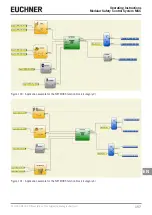
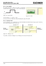
Page 157: ...e original operating instructions Operating Instructions Modular Safety Control System MSC EN Figure 190 Application example for the NETWORK function block category 2 Figure 191 Application example for the NETWORK function block category 4 ...

Page 158: ...tion Figure 193 Reset If the duration is 5 s there is no reset Can be used to reset malfunctions without interrupting the supply to the system 9 5 1 3 Interpage In Out If the circuit diagram is very comprehensive and a connection between to elements that are a long way apart is necessary the component Interpage In Out must be used Left part of the diagram INTERPAGE OUT INTERPAGE IN Right part of t...

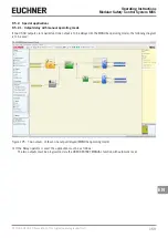
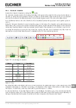
Page 159: ...h manual operating mode If two OSSD outputs are required and one output is to be delayed in the MANUAL operating mode the following diagram is to be used Figure 195 Two outputs of these one output delayed MANUAL operating mode If the Delay operator is used the application must be as follows The two outputs must be programmed via the USER RESTART MANUAL function with automatic reset ...

Page 160: ...trical control systems Ì Ì You will find the safety parameters for the MSC configuration in the report from the software EUCHNER SAFETY DESIGNER In the toolbar at the top there are two new green buttons from firmware MSC CB version 3 0 or higher Figure 196 The buttons for the simulator function These buttons relate to the new simulator function Ì Ì The first button displays the Schematic Simulatio...

Page 161: ...reset the simulation Reset button If the simulation is reset the time is reset to 0 ms On starting the simulation by pressing the Play button the sequence over time can be monitored in the Time field The time elapses as per the Step time unit which is multiplied by the KT factor selected by the user 1 2 3 4 5 6 7 Figure 197 Circuit diagram simulation Number Symbol Description 1 Play button 2 Stop ...

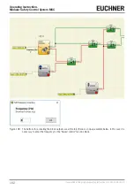
Page 162: ...2 Translation of the original operating instructions 2121331 04 04 19 Figure 198 The buttons for activating the block outputs are at the top there is a pop up example below In this case it is necessary to enter the frequency for the Speed control function block ...

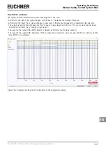
Page 163: ...nished a diagram as shown below appears automatically From the diagram it is possible to print the traces displayed Print button to save the results to load them again Save button and to display other traces Change visibility The identifiers for the traces are the same as in the function block description Click the Close button X button at top right to close the graphic simulation environment Figu...

Page 164: ...ee Figure 42 Template stimuli button Makes it possible to save the template file with the required name in the required storage location on the hard disk This file contains the signal identifiers as per the diagram see Figure 201 Here with the aid of a text editor the operator can enter the status of the input signals at a specific time as well as the duration of the simulation and the time step t...

Page 165: ...ulation completed earlier provided at least one simulation has been saved Traces visibility button Makes it possible to display graphically the traces selected in the form of signal waveforms as a diagram As soon as it is clicked the button opens a pop up window as shown in Figure 203 The traces can be removed from the diagram or added to the diagram in this window Figure 203 Displaying the traces...

Page 166: ...h a delay of two seconds after the start signal Diagram The input elements are represented in the diagram by the door for the safe zone and by the control system for the motor drive These two signals are used as inputs for the AND logic operator the result from this operator is delayed by two seconds by a delay block The relay is then operated by the delayed signal in turn the relay makes it possi...

Page 167: ... changes to logic level 1 It indicates the request for activation by the operator Ì Ì The output signal from the AND operator Op1 changes to logic level 1 at 3000 ms This occurs when the two inputs Safe Zone and Start_Press change to logic level 1 Ì Ì The signal on the output of the AND operator is delayed by 2000 ms by the Delay operator Ì Ì The signal on the output of the delay block Op2 provide...

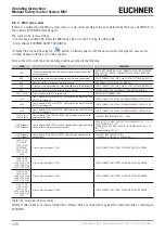
Page 168: ...AY2 for category 4 CHECK CONNECTION OF THE EXTERNAL FEEDBACK CONTACTORS 147D From a module AZ FO4 or AZ FO4O8 EDM error on the pair RELAY2 and RELAY3 for category 4 CHECK CONNECTION OF THE EXTERNAL FEEDBACK CONTACTORS 157D From a module AZ FO4 or AZ FO4O8 EDM error on the pair RELAY3 and RELAY4 for category 4 CHECK CONNECTION OF THE EXTERNAL FEEDBACK CONTACTORS 133D Proxi1 140D Proxi2 From a modul...

Page 169: ...ER FOR REPAIR 139D 148D Error on the module AZ FO4 relay 2 149D 158D Error on the module AZ FO4 relay 3 159D 168D Error on the module AZ FO4 relay 4 128D 191D Error on the encoder interface on the SPM modules RESTART SYSTEM IF THE ERROR PERSISTS SEND THE MODULE TO EUCHNER FOR REPAIR 192D 205D Error OSSD1 206D 219D Error OSSD2 220D 233D Error OSSD3 234D 247D Error OSSD4 Table 79 Overview of error c...

Page 170: ...the loss of the safety function Ì Ì If damage or wear is found the corresponding MSC module must be replaced completely Replacement of individual parts or assemblies is not permitted Ì Ì Check the device for proper function at regular intervals and after every fault For information about possible time intervals refer to EN ISO 14119 2013 section 8 2 No servicing is required Repairs to the device a...

Page 171: ......

Page 172: ...Operating Instructions Modular Safety Control System MSC 172 Translation of the original operating instructions 2121331 04 04 19 ...

Page 173: ......
Page 174: ... euchner de Edition 2121331 04 04 19 Title Operating Instructions Modular Safety Control System MSC Translation of the original operating instructions Copyright EUCHNER GmbH Co KG 04 2019 Subject to technical modifications no responsibility is accepted for the accuracy of this information ...

Reviews: