161
2121331-04-04/19 (Translation of the original operating instructions)
Operating Instructions
Modular Safety Control System MSC
EN
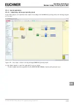
9.6.1. Schematic simulation
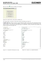
Activate the schematic simulation by clicking the
button.
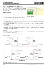
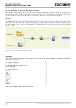
The schematic simulation permits the checking/controlling of the signal on the output from the various function blocks in
real time, i.e. during the actual simulation. The user can select as required which outputs on the blocks are to be operated
and check the reaction of the different elements of the schematic diagram based on the color of the different lines.
As for the Monitor function, the color of the line (or the same button) indicates the signal state: Green signifies signal LL1,
red LL0.
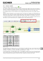
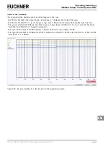
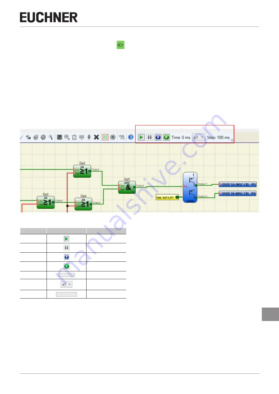
During the "Schematic Simulation" various new buttons appear on the toolbar. The simulation can be administered using
these buttons. They can be used to start the simulation ("Play" button), stop the simulation ("Stop" button), run the simulation
step-by-step ("PlayStep" button) or reset the simulation ("Reset" button). If the simulation is reset, the time is reset to 0 ms.
On starting the simulation by pressing the "Play" button, the sequence over time can be monitored in the "Time" field. The
time elapses as per the "Step" time unit, which is multiplied by the "KT" factor selected by the user.
1 2 3 4 5 6 7
Figure 197: Circuit diagram simulation
Number
Symbol
Description
1
Play button
2
Stop button
3
Play Step button
4
Reset button
5
Time 0 ms
Time
6
KT
7
Step: 100 ms
Simulation step
Table 77: Key
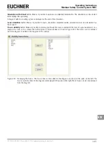
By clicking the button at the bottom right corner of each input block, the related initial status can be activated (also if the
simulation is interrupted, i.e. if the time is not running – the simulation is then "static"). If the button is red after clicking it,
the output is "0" ("LOW") and, conversely, if the button is green the output is "1" ("HIGH").
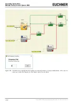
In some function blocks, for example "Speed control" or "Lock feedback", the button is gray. This color indicates that the
value is entered manually using a corresponding pop-up window and the type of value to be entered changes depending on
the type of function block (for example, it is necessary to enter a frequency in the "Speed control" block.)
Summary of Contents for MSC
Page 1: ...EN Operating Instructions Installation and use Modular Safety Control System MSC ...
Page 171: ......
Page 173: ......


