Operating Instructions
Modular Safety Control System MSC
40
(Translation of the original operating instructions) 2121331-04-04/19
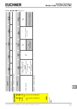
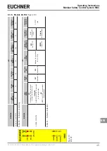
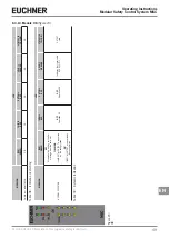
8.3. Signals
8.3.1. Base unit MSC-CB
MEANING
LED
RUN GREEN
IN F
AIL
RED
EXT F
AIL
RED
COM
ORANGE
ENA BLUE
IN1–8 YELLOW
OSSD1/2
RED/GREEN
CLEAR1/2 YELLOW
ST
ATUS1/2 YELLOW
Switch on – initial CHECK
ON
ON
ON
ON
ON
ON
Red
ON
ON
M-A1 detected
OFF
OFF
OFF
ON (max. 1 s)
ON (max. 1 s)
OFF
Red
OFF
OFF
Writing/loading the diagram to/fr
om M-A1
OFF
OFF
OFF
Flashes 5 times
Flashes 5 times
OFF
Red
OFF
OFF
SWSD is r
equesting connec
-
tion: no internal configuration
OFF
OFF
OFF
Flashes slowly
OFF
OFF
Red
OFF
OFF
SWSD is r
equesting connec
-
tion: (extension module or node number not corr
ect) (see
System layout)
OFF
OFF
OFF
Flashes quickly
OFF
OFF
Red
OFF
OFF
SWSD is r
equesting connec
-
tion: (extension module missing or not r
eady), (see System layout)
Flashes quickly
OFF
OFF
Flashes quickly
OFF
OFF
Red
OFF
OFF
SWSD connected, MSC-CB stopped
OFF
OFF
OFF
ON
OFF
OFF
Red
OFF
OFF
Table 20:
Indication on star
ting
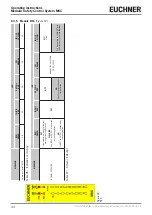
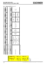
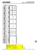
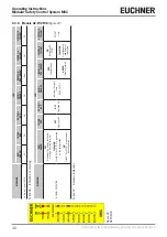
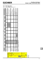
MEANING
LED
RUN GREEN
IN F
AIL
RED
EXT F
AIL
RED
COM
ORANGE
IN1–8 YELLOW
ENA BLUE
OSSD1/2
RED/GREEN
CLEAR1/2 YELLOW
ST
ATUS1/2 YELLOW
NORMAL OPERA
TION
ON
OFF
OFF
Operation
OK
ON
= MSC-CB
connected to PC
OFF
= Other
OUTPUT
state
ON
MASTER_ENABLE1 and MASTER_EN
-
ABLE2 active
OFF
Others
RED
If output OFF
GREEN
If output ON
ON
W
aiting for REST
ART
Flashing
NO feedback
loop
OUTPUT
state
EXTERNAL F
AUL
T DETECTED
ON
OFF
ON
Err
oneous exter
-
nal connection
detected
ON
= MSC-CB
connected to PC
OFF
= Other
Only the number for the INPUT with the err
oneous con
-
nection
flashes
Table 21:
Dynamic indication
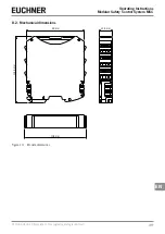
Figur
e 14:
MSC-CB
Summary of Contents for MSC
Page 1: ...EN Operating Instructions Installation and use Modular Safety Control System MSC ...
Page 171: ......
Page 173: ......


