background image


I


O

O

P

P

E

E

R

R

A

A

T

T

I

I

O

O

N

N


M

M

A

A

N

N

U

U

A

A

L

L


U2836 Precision LCR meter


C

C

C

h

h

h

a

aa

n

n

n

g

g

g

z

zz

h

h

h

o

o

o

u

u

u


E

E

E

u

u

u

c

cc

o

o

o

l

ll


E

E

E

l

ll

e

ee

c

cc

t

tt

r

rr

o

o

o

n

n

n

i

ii

c

cc


C

C

C

o

o

o

.

..


,

,,


L

LL

t

tt

d

d

d

.

..


A

AA

d

dd

d

dd

:

:: No.1, Ziyang Road, Tianning District, Changzhou, Jiangsu


T

TT

e

ee

l

ll

:

::

0

00

5

55

1

11

9

99

8

88

5

55

5

55

0

00

5

55

1

11

9

99

9

99


F

FF

a

aa

x

xx

:

::

0

00

5

55

1

11

9

99

8

88

5

55

5

55

0

00

5

55

1

11

6

66

9

99


E

EE

-

--

m

m

m

a

aa

i

ii

l

ll

:

::


S

SS

a

aa

l

ll

e

ee

s

ss

@

@

@

e

ee

u

uu

c

cc

o

oo

l

ll

.

..

c

cc

o

oo

m

m

m

.

..

c

cc

n

nn


W

W

W

e

ee

b

bb

s

ss

i

ii

t

tt

e

ee

:

::


h

hh

t

tt

t

tt

p

pp

:

::

/

//

/

//


w

w

w

w

w

w

w

w

w

.

..

e

ee

u

uu

c

cc

o

oo

l

ll

.

..

c

cc

o

oo

m

m

m

.

..

c

cc

n

nn


Summary of Contents for U2836

Page 1: ...d d No 1 Ziyang Road Tianning District Changzhou Jiangsu T T Te e el ll 0 0 05 5 51 1 19 9 9 8 8 85 5 55 5 50 0 05 5 51 1 19 9 99 9 9 F F Fa a ax x x 0 0 05 5 51 1 19 9 9 8 8 85 5 55 5 50 0 05 5 51 1...

Page 2: ...1 MEAS DISP 8 2 4 2 MEAS SETUP 8 2 4 3 SYSTEM 8 2 5 Basic Operation 8 2 6 Start the instrument 9 Chapter 3 Introduction to MEAS DISP 10 3 1 MEAS DISPLAY 10 3 1 1 Test function 11 3 1 2 Test range 12 3...

Page 3: ...INFORMATION 33 4 1 12 FIRMWARE UPDATE 34 4 1 13 SYSTEM TEST 34 4 2 FILE 35 4 2 1 Setup file for single group component EST 35 4 2 2 U disk manage performance 36 4 2 3 Operation steps for file managem...

Page 4: ...ation resistance 50 6 4 2 Insulation intensity 51 6 4 3 Leakage current 51 6 5 Electromagnetic compatibility 51 6 6 Performance test 51 6 6 1 Working condition 51 6 6 2 The used instruments and device...

Page 5: ...panel 2 Power supplying frequency range 47 63Hz 3 Power supplying power range less than 20VA 4 Power supplying input phase line L zero line N ground lead E should be as same as the power plug of the i...

Page 6: ...5 and 40 humidity is less than 85 RH If the instrument will not be put in use for a time please have it properly packed with its original box or a similar box for storing 6 The instrument especially t...

Page 7: ...U2836 Operation Manual Chapter 1 Out of Box Audit 3 1 7 Other features 1 Power consumption power 20VA 2 Dimension W H D 280mm 88mm 320mm 3 Weight About 3 5kg...

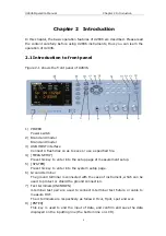
Page 8: ...o save or use a specified file 4 MEAS SETUP Press this key to enter into the setup page of measurement setup 5 SYSTEM Press this key to enter into the system setup page 6 Ground terminal The ground te...

Page 9: ...ic of the input value 14 Numerical keys These keys are used to input data to the instrument The key consists of numerical keys 0 to 9 decimal point and key 15 FAIL indicator LED indicator shows the te...

Page 10: ...ing used to install power fuse protect instrument Warning Be sure that the direction of fuse is accordant with power supply voltage range before charging 5 Ground terminal The ground terminal is conne...

Page 11: ...esponding specific tools 3 System icon zone In this zone display the system status U disk is connected Romot control status Keyboard locked Data recording status 4 Soft keys The zone is used to displa...

Page 12: ...to enter into the system setup page The following soft keys will be available SYSTEM SETUP SYSTEM INFO FIRMWARE UPDATE SYSTEM TEST FILE LIST 2 5 Basic Operation Basic operation of U2836 is as follows...

Page 13: ...supply voltage and frequency conform to above specifications Power input phase line L zero line N ground line E should be the same as that of the instrument Press the power switch at the left corner o...

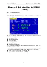
Page 14: ...arameters can be set in this page Test function FUNC Test frequency FREQ Test level LEVEL Test range RANGE Test speed SPEED Output impedance RSOU There are 6 zones in this page FUN FREQ LEVEL RANG SPE...

Page 15: ...parameters are respectively displayed in two lines in the form of upper case characters The primary parameter displays in the upper line while the secondary parameter displays in the lower line Opera...

Page 16: ...he soft key is used to decrease the range under HOLD mode 2 Use soft keys to set measurement range 3 1 3Test frequency The measurement range of U2836 ranges from 50Hz to 200kHz total 37 frequency poin...

Page 17: ...e is to use soft keys while the second one is to input data by numeric keys 1 Move the cursor to LEVEL the following soft keys will be displayed INCR This soft key is used to increase the level of tes...

Page 18: ...ursor to TOOL zone the following soft keys will be displayed D P FIX A D P FIX B DISP OFF ON EASY START SAVE CSV 2 Press D P FIX A to lock the decimal location of primary parameter TEST result When th...

Page 19: ...alue HIGH LOW 3 2 1Comparator function U2836 has an inserted compare function which can divide DUT to up to 4 bins from BIN1 to BIN3 and BIN OUT Users can set 3 pairs of primary parameter limit and on...

Page 20: ...er will be displayed in the help zone Then the following soft keys will be displayed YES NO 5 Press the soft key YES to reset all bin counts to 0 6 Press the soft key NO to cancel the reset operation...

Page 21: ...r Mode TRIG Delay Time DELAY Average times AVG Auto LCR Function AUTO LCR Voltage Level Monitor ON OFF MON 1 Current Level Monitor ON OFF MON 2 Deviation Test Mode A DEV A Deviation Test Reference Val...

Page 22: ...f testing when U2836 receives a trigger signal it will be ignored So the trigger signal should be sent after the test is done When optional HANDLER interface triggers U2836 the trigger mode is set as...

Page 23: ...the correction is switched between OPEN or SHOR the level monitor value will be influenced as well Operation steps for setting the monitor function Execute the following operation steps to set the lev...

Page 24: ...test terminal has a reliable contact Operation steps for setting the delay function Execute the following steps to set the measurement delay time 1 Move the cursor to the DELAY zone 3 the following so...

Page 25: ...percentage of the difference between the test value of DUT and the preset reference value divided by the reference value Its calculating formula is as below X Y Y 100 Where X is the test value of DUT...

Page 26: ...f the secondary parameter 3 4 CORRECTION Open and short correction can be used to eliminate the distribution capacitance spurious impedance and other measurement errors U2836 provides two correction m...

Page 27: ...inductance under 37 frequencies It will take about 20 seconds to finish the open full frequency correction In the process of correction the following soft key will be displayed CANCEL This soft key ca...

Page 28: ...ction on the current frequency 5 Press the SWEEP SHORT soft key U2836 will test the short spurious impedances resistance and reactance of 37 frequencies Short full frequency correction takes about 20...

Page 29: ...parameter FUNC Limit mode of compare function MODE Nominal value NOM Auxiliary bin ON OFF AUX Compare function ON OFF COMP Low limit of each bin LOW High limit of each bin HIGH 3 5 1Swap parameter Th...

Page 30: ...alue The compare limit value should be set in the order from small to large Figure 3 3 Tolerance mode and Sequential mode Note When setting limit values of tolerance mode the error range should be set...

Page 31: ...ER key to input the nominal value Press 1 to input nominal value the instrument will select F H or as the default unit of the nominal value according to primary parameter 3 5 4Comparator function ON O...

Page 32: ...w limit the DUT will be sorted into the auxiliary bin When the secondary parameter only has high limit and the auxiliary bin is set as ON if the primary parameter of DUT is within the limit range and...

Page 33: ...the high limit of the secondary parameter 7 In Low limit of BIN 1 use numeric keys to input the low limit After inputting the data you can use p n m k M 1 to replace ENTER to input the limit value Whe...

Page 34: ...te data time 4 1 1SKIN The function of this zone is to set the theme of display Operation steps for setting the theme of display 1 Move the cursor to SKIN the following soft keys will be displayed GRA...

Page 35: ...s used to select short beep TWO SHT This soft key is used to select two low and short beeps 4 1 4FAIL ALARM This zone is used to control and display the beep mode as FAIL ALARM when the test result is...

Page 36: ...t user s file MODIFY This soft key is used to modify the password The operation steps are as follows Press MODIFY to input a new password After inputting a prompt information will appear on the screen...

Page 37: ...interface The available baud rate of this instrument is from 4 800k to 115 200k Operation steps for setting the baud rate 1 Move the cursor to BAUD RATE the following soft keys will be displayed 1200...

Page 38: ...ess FIRMWARE UPDTE enter into the FIRMWARE UPDATE page shown as below 2 Press UPDTE the following soft keys will be displayed YES NO 3 Press YES soft key to update the firmware of the instrument 4 1 1...

Page 39: ...ransformer scanning will be described in the part of transformer test setting Press FILE to enter into the file manage page shown as below 4 2 1Setup file for single group component EST 100 groups of...

Page 40: ...be copied to IBM PC or compatible desk top computer laptop with USB interface to reach the infinite extension U2836 supports the USB memory devices as below Meet the USB 1 0 1 1 standard Capacity 32MB...

Page 41: ...ps 1 Assuming that it is necessary to copy internal files 2 and 3 to files 12 and 13 respectively 2 Press FILE the file list and the following soft keys will be displayed LOAD SAVE DELETE COPY RENAME...

Page 42: ...an 0 1 before connecting to DUT it is recommended to connect Hcur Hpot and Lpot Lcur Two terminal test In the test with high accuracy requirement using Kelvin test fixture standard accessory will gain...

Page 43: ...o as to avoid the damage to the instrument 5 2 Eliminate the influence of stray impedance Figure 5 2 Eliminate the influence of stray capacitance When the DUT has high impedance such as small capacita...

Page 44: ...een test leads becomes the main source of test errors except the influence of the contact resistance on test terminals If this coupling cannot be eliminated it will bring unexpected influence on test...

Page 45: ...zone Press kHz the frequency will be changed as 5 000kHz g Move the cursor to LEVEL zone the current displayed level will be 1 000V h Press 1 5 1 5 will be displayed in the prompt information zone at...

Page 46: ...the tested inductance is in good connection with the test fixture or not b Check the test fixture is in good connection with the test terminals of the instrument or not c Redo the open short correcti...

Page 47: ...es Primary parameter Z Y L C R G Secondary parameter deg phase rad radian D Q RS RP G X B 6 1 3Mathematical operation Operation between the measurement value and the programmable nominal value absolut...

Page 48: ...uency 10kHz Fast about 40 times s 27ms time Medium about 10 times s 90ms time Slow about 3 times s 300ms time The fast and middle speed will be slow down when frequency 10kHz 6 1 10 Average Be program...

Page 49: ...01 H 99 9999kH C 0 00001pF 9 99999F Z R X 0 00001 99 9999M Y B G 0 00001 s 99 9999S D 0 00001 9 99999 Q 0 00001 99999 9 Deg 179 999 179 999 Rad 3 14159 3 14159 6 3 Measurement accuracy Test accuracy i...

Page 50: ...Q test value 0 1 WhenDx 0 1 L C X B accuracy factor Ae should be multiplied by 2 1 x D When Qx 0 1 R G accuracy factor Ae should be multiplied by 2 1 x Q Accuracy of G can only be available in G B co...

Page 51: ...p G combination 6 3 6 Accuracy of Rp when Dx value of tested D 0 1 The accuracy of Rp is given by the formula below Rp e x e px D D D R m Where Rpx is the value of tested Rp with the unit S Dx is the...

Page 52: ...ure A select a smaller value on boundary line In this figure the basic accuracy value A can be obtained by the following methods 0 1 When 0 4Vrms Vs 1 2Vrms the test speed is the value A of medium slo...

Page 53: ...V Z 100Hz fm 100kHz 200 1 10 1 3 s m V Z 70 1 10 1 9 s m V Z 100kHz f m 200kHz 200 2 10 1 3 s m V Z 70 1 10 3 9 s m V Z Fast fm 100Hz 100 1 400 1 10 5 2 3 m s m f V Z 100 1 100 1 10 2 9 m s m f V Z 1...

Page 54: ...length 0m 1m 2m 1 5Vrms 0 2 5 10 4 1 50 fm 5 10 4 1 50 fm 1 5Vrms 0 2 5 10 3 1 16 fm 5 10 3 1 50 fm fm test frequency MHz Table E Temperature factor Ke Temperature 5 8 18 28 38 Ke 6 4 2 1 2 4 6 3 9 A...

Page 55: ...be larger than 3 5mA AC effective value 6 5 Electromagnetic compatibility Transient sensitivity based on the requirement of GB6833 4 Conductive sensibility based on the requirement of GB6833 6 Radiate...

Page 56: ...Standard inductor 100 H 0 02 1mH 10mH 100mH 5 Frequency counter 0 1000 MHz 6 Digital Multimeter 0 5 7 Insulation resistance meter 500V 10 levels 8 Hipot Tester 0 25kW 0 500 V 6 6 3 Function check Ens...

Page 57: ...pectively Level 1V Range AUTO Bias 0V Speed Slow Open and short correction should be made before testing Connect standard capacitors 100pF 1000pF 10nF 0 1uF 1uF and change the frequency The error capa...

Page 58: ...z 1kHz 10kHz 100kHz Test respectively Level 1V Range AUTO Bias 0V Speed Slow Open and short correction should be made before testing Connect standard AC resistors 10 100 1k 10k 100k and change the fre...

Reviews: