U2836 Operation Manual Chapter 5 Execute LCR operation and some examples
49
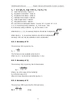
Figure B is the basic accuracy modification curve, where V
s
is the test signal
voltage.
10m
20m
50m
5m
100m
200m
500m
1
2
3
1
2
5
10
20
50
100
1.2
150m
Ar
[Vrms]
Table A Impedance rate factors: K
a
, K
b
Speed Frequency
K
a
K
b
Medium
Slow
f
m
<
100Hz
)
100
1
)(
200
1
)(
10
1
(
3
m
s
m
f
V
Z
+
+
×
−
)
100
1
)(
70
1
)(
10
1
(
9
m
s
m
f
V
Z
+
+
×
−
100Hz
≤
fm
≤
100kHz
)
200
1
)(
10
1
(
3
s
m
V
Z
+
×
−
)
70
1
)(
10
1
(
9
s
m
V
Z
+
×
−
100kHz<f
m
≤
200kHz
)
200
2
)(
10
1
(
3
s
m
V
Z
+
×
−
)
70
1
)(
10
3
(
9
s
m
V
Z
+
×
−
Fast
f
m
<
100Hz
)
100
1
)(
400
1
)(
10
5
.
2
(
3
m
s
m
f
V
Z
+
+
×
−
)
100
1
)(
100
1
)(
10
2
(
9
m
s
m
f
V
Z
+
+
×
−
100Hz
≤
fm
≤
100kHz
)
400
1
)(
10
5
.
2
(
3
s
m
V
Z
+
×
−
)
100
1
)(
10
2
(
9
s
m
V
Z
+
×
−
100kHz<f
m
≤
200kHz
)
400
2
)(
10
5
.
2
(
3
s
m
V
Z
+
×
−
)
100
1
)(
10
6
(
9
s
m
V
Z
+
×
−
Where, f
m
is the test frequency and the unit is [Hz].
The unit of the tested impedance is [
Ω
].
The unit of the test signal voltage is [mV
rms
].
When the impedance is smaller than 500
Ω
, K
a
, K
b
is unavailable.
When the impedance is larger than 500
Ω
, K
a
, K
b
is unavailable.


