ENGINEER SELECTABLE FUNCTIONS
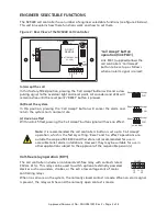
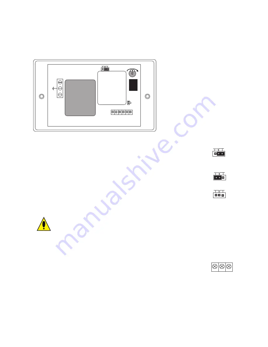
The NC943B call controller has a number of engineer selectable functions (see figure 3 below).
This section explains how these functions work and how to set them.
Figure 3 : Rear View of the NC943B Call Controller
(a) Accept the call
In this factory-fitted position, pressing the ‘Call Accept’ button will send a slow
pulsing signal to the overdoor light and reset point. All sounders and LEDs will
remain active until the reset point’s ‘RESET’ button is pressed.
(b) Reset the system
In this position, pressing the ‘Call Accept’ button will cancel the alarm and
return the system to its normal state.
(c) Have no effect
With no link fitted, pressing the ‘Call Accept’ button signal will have no effect.
Note:
It is recommended the call controller’s button is set up to ‘Call Accept’
operation, which is the factory setting. ‘Reset’ and ‘no effect’ operations are
outside the scope of BS 8300 and therefore not recommended for use in
accessible toilet alarm installations. However, they may be suitable for use in
other applications subject to the approval of the responsible person(s).
Volt-free relay operation (RLY1)
The call controller includes an on-board volt-free relay with contacts rated
30Vd.c. @ 1A. This relay can be used to switch optional externally powered
devices such as sounders, strobes, or the extra low voltage coils of mains
controlling relays.
When no calls are on the system, the normally closed contact is made. When an alarm signal
is present, the relay switches and the normally open contact is made.
‘Call Accept’ button
operation (link PLK1)
Link PLK1 (supplied) allows the
call controller’s ‘Call Accept’
button to be set up as follows
when an alarm signal is raised:
L
N
Volume
+V
E
S
IG
N
A
L
-V
E
N
O
C
N
C
DO NOT
REMOVE
(BATTERY BACKUP
COVER)
Fit to
Enable
battery
PLK2
CONN3
CONN2
VR1
RLY1
Accept
Reset
PLK1
Reset
Accept
PLK1
Reset
Accept
PLK1
Reset
(no link fitted)
Accept
PLK1
Approved Document No.: DNU0951001 Rev 3 • Page 5 of 8
NO
C
NC
CONN3

