SD20-G Series
226
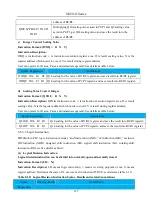
Addr.
Content
Addr.
Content
B464
High-speed timer 1out
B465
High-speed timer 2out
B466
High-speed counter 1out
B467
High-speed counter 2out
B468
High-speed timer 1 reset
confirmation
B469
High-speed timer 2 reset
confirmation
B470
High-speed counter 1
reset confirmation
B471
High-speed counter 2 reset
confirmation
R30
~
R255
B464
B4095
User space
6.8.3 Built-in PLC Program Design
Built-in PLC program design is the special instruction of servo drive, customer should program the
instructions in strict accordance with the following descriptions, otherwise, instruction compilation error
could happen.
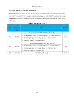
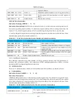
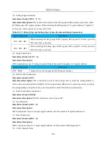
Table 6.8.1 Part of Instructions Abbreviation
Name
Content
B□□
PLC internal storage bit addressing address
P□□
Servo parameter address
R□□
PLC internal storage 16-bit addressing address
D□□
16-bit signed number
L□□
32-bit signed number
6.8.3.1 Data Move Instruction
The data moveinstruction is to transfer the source operands of register into the register assigned by
destination operands. The data transfer instruction of SD20 built-in PLC includes 16-bit and 32-bit, will
be introduced respectively as follows:
(1)
16-bit Move Instruction
Instruction Format
:
[MOVW□□ X Y]
Instruction Description:
MOVW is move instruction code, □□ is instruction execution register area, X is execution operating
register address, Y is destination register address; After executing instructions, the result is Y=X;
□□ can be changed for register area according to practical operation, movable area includes R area, P area
and immediate operand; See details in table 8.1.1
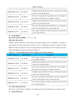
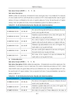
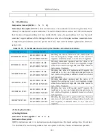
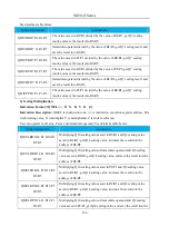
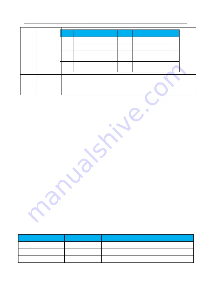
Table 8.1.1 16-bit Move Instruction Syntax, Results and relatedAnnotations
Syntax Expression
Running Results
Annotations
MOVWRR R10 R2
R2=R10
Data transfer in R area;
MOVWDR D10 R1
R1=10
Immediate operand transfers to R area no.1 register;
MOVWPR P1 R10
R10=Po001
Content of no.1 register in P area transfers to no.10
Summary of Contents for SD20-G Series
Page 35: ...SD20 G Series 35 M3 structure Fig 3 1 5 Servo drive structure 3...
Page 36: ...SD20 G Series 36 ML3 structure 118 5 5 7 5 93 297 8 223 118 93 0 5 12 5 7 5 4 M4...
Page 38: ...SD20 G Series 38 M4 structure Approx mass 10 365 kg Fig 3 1 7 Servo drive structure 5...
Page 39: ...SD20 G Series 39 M5 structure Approx msaa 11 1Kg Fig 3 1 8 Servo drive structure 6...
Page 40: ...SD20 G Series 40 M6 structure Approx mass 17 4Kg Fig 3 1 9 Servo drive structure 7...
Page 182: ...SD20 G Series 182 Fig 6 4 44SD20E Cam internal frameworkdiagram...

