background image

 21 


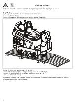
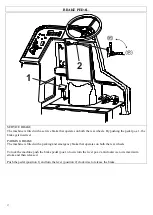
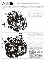
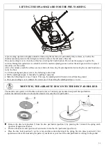
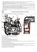
FILLING THE DETERGENT SOLUTION TANK 

 
The solution tank can only be filled with clean water when the detergent dosing system is used, or with a mix of water 
and  detergent  suited to  the  type  of floor  and  to  the  conditions  of  dirt to  be  washed  and  a  product  suitable  for reducing 
foam.  


1

2

3

4


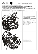
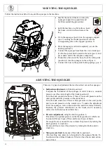
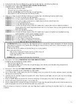
Stop the machine on a flat floor area, 
turn off the ignition key and engage the 
brake;  


Open the seat hood (pos. 2) by releasing 
the safety catch (pos.6); 


Open the tank lid (pos.4) by means of 
the button (pos.3) which controls an 
electric actuator. 


1

2

3


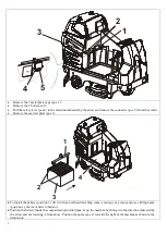
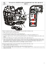
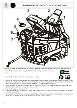
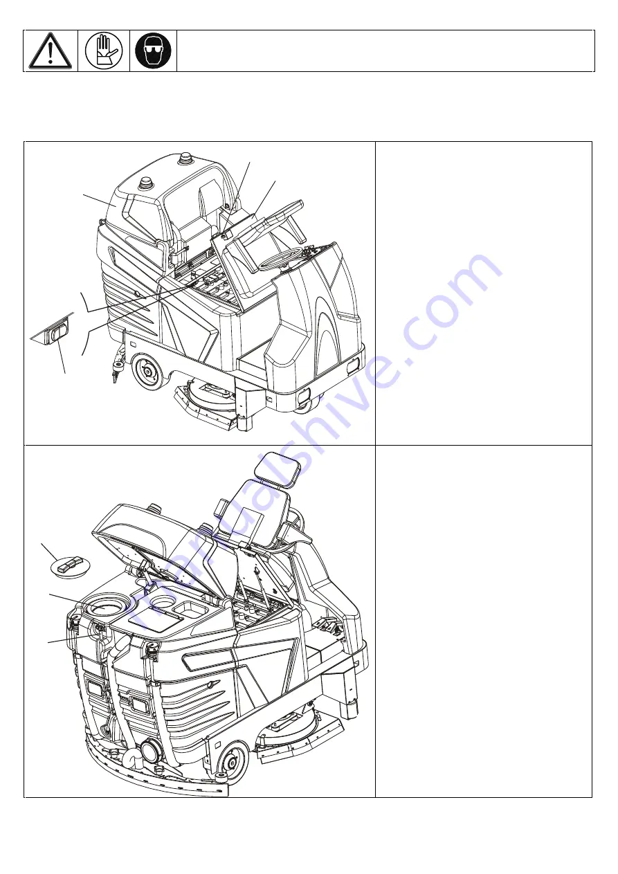
Loosen the cap (pos. 1) and remove it; 


Only fill the tank with clean water, with 
a temperature below 40°C, in the event 
of the detergent dosing system being 
used.  


In the event of the detergent dosing 
device not being used: 
•  Pour the detergent solution into the 
tank directly. Look at the instructions on 
the package to determine how much 
detergent solution to use, how to mix the 
solution and what safety precautions to 
take before using the product. Make sure 
to use low-foaming liquid detergents or 
appropriate products to cut-down foam.


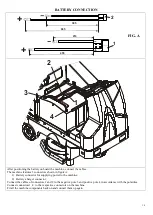
•  After pouring the detergent solution, 
fill the tank with water. Make use the 
water used to fill the tank does not 
exceed 40°C. 


WARNING: 

DO 

NOT 

POUR 

INFLAMMABLE  LIQUIDS  INTO 
THE TANK 

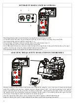
•  After filling the tank, place the 
device (pos 1) The level of the water or 
of the solution in the tank can be seen 
through the level pipe (pos. 3).   


Summary of Contents for 110-R/D

Page 1: ...USE 25 OPERATION 25 PERIODIC SERVICING 27 DRAINING AND CLEANING THE RECOVERY TANK 27 ECO SYSTEM PLANT WASHING INSTRUCTIONS 28 DRAINING AND CLEANING THE SOLUTION TANK 29 CHECKING BRUSHES OR ABRASIVE DI...

Page 2: ...dition These are normal maintenance measures that any operator will be able to carry out with implements that he or she should normally have in the company In the case of particularly demanding work p...

Page 3: ...DINARY SERVICING CLEAN REPAIR AND TRANSPORT THE MACHINE OUR COMPANY WILL NOT BE HELD LIABLE FOR ANY PROBLEMS BREAKAGE ACCIDENTS OR OTHER OCCURRENCES DUE TO THE IGNORANCE OR THE NON APPLICATION OF THE...

Page 4: ...temperature range of 5 C 40 C keep the machine within a humidity range of 30 C 80 C PRECAUTIONS FOR THE SAFETY OF OPERATORS AND TECHNICIANS The machine must not be used by non authorized personnel wh...

Page 5: ...be considered harmful toxic waste they must be given only to Collectors with specific authorization to be checked at the time of consignment SCRAPPING OF THE MACHINE When the machine is to be scrappe...

Page 6: ...NOTICE brushes discs and disc pad holders must be purchased separately Follow the instructions below to unpack the machine connect the inclined ramp to the front part of the pallet as shown in the fi...

Page 7: ...MUST BE SET CONTACT A RESELLER OR A TECHNICIAN BEFORE MOUNTING THESE TYPES OF BATTERIES Refer to the specification sheet for battery types and sizes suitable for the machine 1 2 3 4 5 Follow the instr...

Page 8: ...3 1 2 3 4 To install the battery position 3 lift it with an overhead travelling crane a carriage or a crane and use a lifting beam position 1 chains or belts to fasten it Position the battery inside...

Page 9: ...tors shown in figure A 1 Battery connector for supplying power to the machine 2 Battery charger connector Connect the cables of connectors 1 and 2 to the negative pole 3 and positive pole 4 in accorda...

Page 10: ...YSTEM safety filter 15 Squeegee maximum pressure adjustment 16 ECO SYSTEM filter 17 ECO SYSTEM floating device 18 Max level floating device of the recovery tank 19 Rear wheel 20 Splashguard 21 Brush t...

Page 11: ...Control panel 11 Battery charger cable 12 Cooling fan battery recharge phase 13 Battery charger 14 Pedal brake 15 Solution pump 16 Detergent can 17 Detergent can compartment 18 ECO SYSTEM solenoid va...

Page 12: ...er the 5 green led lights on the panel come on progressively one at a time Each led light is associated with a maximum pre set quantity of water Press the button to decrease the quantity of water the...

Page 13: ...ecovery tank goes below the minimum level required for the ECO SYSTEM function all five led lights on the water metering unit will start flashing and the brushes will stop operating 4 CHARGE BATTERY L...

Page 14: ...nformation will appear on the display in successive order THE BUTTONS ON THE INSTRUMENT PANEL AND THE DRIVE CONTROLS SHOULD NEVER BE TOUCHED DURING THIS SEQUENCE The charge level of the battery will a...

Page 15: ...this occurs the five led lights on the solution metering pump will start flashing and the brushes function will be deactivated 20 EXTRA PRESSURE BUTTON Press this button to increase pressure on the b...

Page 16: ...brake gets inserted PARKING BRAKE The machine is fitted with a parking and emergency brake that operates on both the rear wheels To lock the machine push the brake pedal pos 1 down turn the lever pos...

Page 17: ...anel pos 3 Slowly push forward the drive control pos 6 The brush motors will start rotating and the machine will start to move slowly Go forward for a brief distance and then go in reverse drive using...

Page 18: ...ent with knob position 2 It adjusts the inclination of the squeegee in order to have a constant pressure over the entire length of the blade position 1 Turn the knob counter clockwise if there is too...

Page 19: ...20 POS 1 NORMAL SITUATION POS 1 POS 2 ENABLE YOU TO WORK NEXT TO THE WALLS AND TO TURN LEFT OF 90 NEAR THE CORNER POS 2...

Page 20: ...h clean water with a temperature below 40 C in the event of the detergent dosing system being used In the event of the detergent dosing device not being used Pour the detergent solution into the tank...

Page 21: ...pipe pos 4 making sure the filter reaches the bottom so as to suction up all the detergent in the can Block the pipe pos 4 by means of the cone pos 5 inserting it in the can with a slight pressure FI...

Page 22: ...e This operating principle is also applied to the detergent dosing system ADJUSTING THE QUANTITY OF SOLUTION ON THE BRUSHES CHEMICAL 1 5 2 3 4 1 ON OFF 1 2 The max quantity of the solution on the brus...

Page 23: ...ashguard pos 1 manually by pulling it upwards Make the 4 blocking lever pos 2 rotate This way the splashguard will remain raised from the ground Once pre washing is over unfasten the screws pos 2 thus...

Page 24: ...tarts flashing this means that there is an over absorption of the motors After 1 minute with the flashing led light the writing E1 appears on the control board The brushes will stop lifting the plate...

Page 25: ...queegee leaves wet lines on the floor during the washing operation it means that there are pieces trapped beneath the rear rubber wheels of the squeegee Lift the squeegee and remove the trapped pieces...

Page 26: ...N OFF button and go to the tank drainage area Turn off the machine remove the key and put on the brake Open the hood of the seat pos 1 by releasing the special safety hook Open the tank lid pos 2 by l...

Page 27: ...y in order to prevent encrustation formation inside the pipe CLEANING INSTRUCTIONS ECO SYSTEM At the end of each working day take the machine to the tank draining area 1 2 3 4 6 7 CHEMICAL 1 5 2 3 4 1...

Page 28: ...w Part of the pipe is flexible position 7 and therefore it can be squeezed to limit the water flow Once opened lay the pipe on the ground slowly After completing the cleaning procedures open the hood...

Page 29: ...on tank In theory the solution located in this tank should not have any impurities as the buckets or containers used to fill the solution are supposed to be clean in addition there is a filter in the...

Page 30: ...emove any pieces or incrustations from the lower part and from the mouth of the squeegee see position 5 Use a piece of cloth to wipe off the rear drying blade see position 4 and the front drying blade...

Page 31: ...d remove the 6 screws and the respective washers see position 2 Remove the blade locking plate see position 3 Remove the blade see position 4 Rotate the blade and mount it back so that a new edge is o...

Page 32: ...cking plate position 3 Remove the right side blade position 2 rotate it 180 and put it back into place if the external edge is in good condition otherwise replace it with a new one Put the rubber and...

Page 33: ...osition in a flat surface area and put on the brake Lower the brush plate pos 3 by pressing the special button in the control board With the lowered plate turn off the machine and remove the key Press...

Page 34: ...eed as follows Bring the machine into a stop position in a flat surface area turn the key in pos 0 and put on the brake Press the emergency button pos 19 Remove the 6 locking screws pos 16 from the fu...

Page 35: ...use BRUSH MOTORS PROTECTION ATTENTION This fuse is used by the function card to control the correct absorption of brush motors amperometric protection It is possible that although the motor reducers w...

Page 36: ...ECK THE OIL LEVEL OF THE DRIVE WHEEL REDUCER 1 Check the oil level by removing the level oil cap Pos 1 2 If necessary fill up the wheel reducer with SYNTHETIC OR MINERAL OIL SAE 80W90 up to the level...

Page 37: ...from its seat Wash the filter with water and dry it using hot air be careful not to damage it Put the air filter back into place pos 2 Lower the locking filter handwheel pos 1 Turn the machine on and...

Page 38: ...l be displayed including the type of battery and the set charge curve pos 10 the size of the battery charger pos 9 the recharge voltage pos 11 the recharge amperage pos 8 charged amps pos 1 recharge t...

Page 39: ...att 36 600 WATER LIFT mm H2O 1800 TRACTION ELECTRONIC DRIVE BY MEANS OF DIFFERENTIAL MOTOR V Watt 36 2600 FRONT WHEEL WITH STEEL CORE FULL RUBBER TYPE NON MARKING OIL PROOF 300 X 100 REAR WHEELS WITH...

Page 40: ...THE USER HIMSELF ON CONDITON IT HAS PREVIOUSLY BEEN INSTRUCTED BY EITHER THE MACHINE OWNER OR HIS EMPLOYER 360424 360425 360430 210474 210474 360426 360427 360431 360419 360418 360428 360428 520084 TE...

Page 41: ...E OF LINATEX OF 6 35mm OPTIONAL COD 360448 SQUEEGEE FRONT BLADE OF LINATEX OF 4 76mm STANDARD COD 360426 SQUEEGEE REAR BLADE OF LINATEX OF 9 52 mm OPTIONAL COD 360428 LEFT RIGHT BLADE COD 360447 SQUEE...

Page 42: ...Replace it Follow the instructions at pag 46 E1 Replace it Replace it Replace it By pressing the extra pressure button the brush plate does not get into correct position 24 Faulty actuator 25 Faulty c...

Page 43: ...unctioning of the drive electric control is blinking 72 Diagnosis for led flashings ON NO ERRORS NORMAL CONDITION OFF ERROR INSIDE THE REMOTE SWITCH Replace it 1 FLASHING personalization out of spec C...

Page 44: ...ervice supply remote switch faulty Replace Have it replaced Replace it Replace it Have it replaced Reverse lights not working 111 Light faulty 112 Reverse light relay faulty 113 Fuse carrier 5A fuse p...

Page 45: ...es contact your dealer or a technician Alarm when starting up the machine the brushes actuator does not reach the pos 0 within the max lapse of time 10 sec Make sure that no foreign bodies are prevent...

Page 46: ...o the machine and or parts which have been repaired or altered outside Eureka s plant or the facility of Eureka s Authorized Sales Service Representative This warranty does not apply to routine wearab...

Page 47: ...TALLATION DATE GENERAL INFORMATION 1 HAS THE LEAD TIME BEEN RESPECTED 4 HAVE YOU READ THE OPERATION MANUAL PRIOR TO USING THE MACHINE 2 HAVE YOU BEEN SHOWN HOW TO USE THE MACHINE 5 HAVE YOU BEEN OFFER...

Page 48: ...nimi per evitare lo schiacciamento di parti del corpo UNI EN 349 Sicurezza degli apparecchi elettrici d uso domestico e similare Parte generale EN 60335 1 1994 A11 1995 A1 1996 A2 2000 A13 1998 A14 19...

Reviews: