

16
4
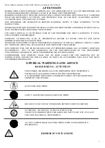
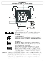
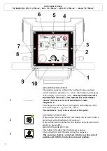
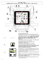
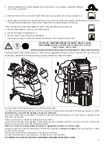
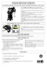
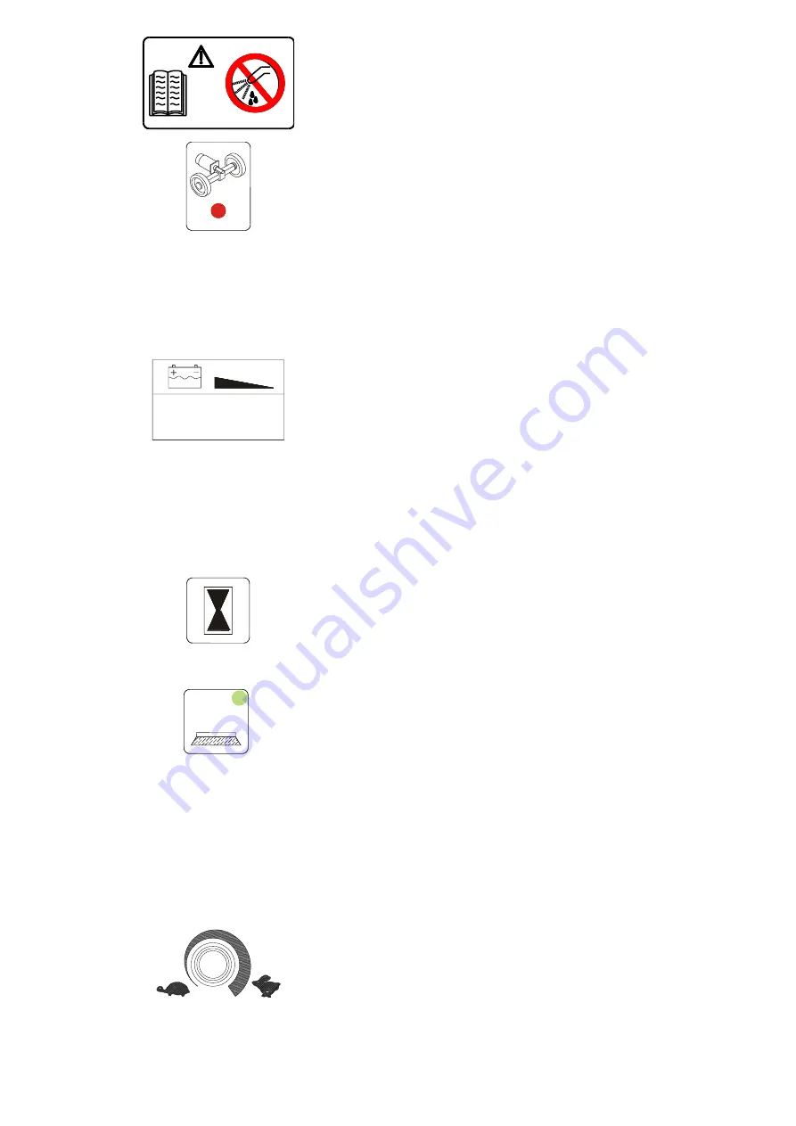
WARNING SYMBOLS
The symbol on the left advices using the instruction manual at all
times for any information regarding the machine, whereas the
symbol on the right forbids washing the instrument panel with
heavy water jets as there are electrical parts.
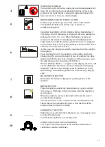
5
RED WARNING LIGHT: DRIVE ALARM
It shows any anomalies present on the motor’s drive board.
The number of blinks indicates the type of fault (see
troubleshooting table).
6
CHARGE BATTERY LEVEL INDICATOR AND DISPLAY
The charge level of the battery is displayed when the machine is
switched on (100 – 90 – etc). When the battery charge level
reaches 20, the number on the display starts blinking and the
brush operation is disabled since a protection device is triggered
to prevent the battery from getting damaged, however the suction
and drive functions remain active.
At this point, the brush plate shall be raised and the floor shall be
dried quickly.
Upon reaching level 10, the number on the display shall start
blinking and the suction function will also be disabled, the drive
function will be the only active function. Lift the squeegee, go to
the tank drainage area and charge the batteries.
When 4 blinking dashes (----) appear on the display, the drive will
also be disabled as the battery reaches a minimum discharging
threshold. Therefore, the machine must be pushed over to the
tank drainage area and then pushed over to the battery charging
area.
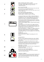
7
HOUR METER BUTTON
Hold down this button to display the operating hours of the
machine.
8
.
BRUSH BUTTON
Press this button to enable the brush function; a green led light
will come on. The brush will start rotating when the machine is
set in motion.
When the control is released, the brush will rotate for other 3
seconds before stopping.
The solenoid valve is also connected to the brush function and
allows the user to automatically open or shut the flow of the
solution while the brush is rotating.
9
----------
EMERGENCY BUTTON
This button is used to halt the machine in case of emergency and
to lock all its functions.
Turn the knob clockwise to reset the power.
10
SPEED ADJUSTING POTENTIOMETER
To set up the maximum speed of the machine turn the knob
clockwise or counter-clockwise.


