ELECTRIC MOTOR
STARTING THE ENGINE
Turn the key in pos.1 (fig.2 pos.C)
HOW TO CHARGE BATTERIES
• Turn off the machine
• Remove the key from the switch and open the machine’s hood
• Disconnect the plug (fig. 2 pos. F)
• Connect the battery charger’s plug (fig. 2 pos. H)
• Charge the batteries to a level not above 1/10th of their capacity.
• Check level of electrolyte and top it up, if necessary, with water.
• When the batteries are charged, connect again the connector (fig. 2 pos. F)
BATTERY CHARGE INDICATOR (FIG.2 POS.D)
It monitories the level of charge of the battery. While the green led is on,
you can sweep. When the yellow led gets on, you must take care to go to
have the battery charged. When the red led gets on, you must immediately
switch off the machine, because the battery, if further discharged, can get
irreversibly damaged its structure.
STOPPING THE ENGINE
Turn the key in pos.0 (fig.2 pos.C)
WARNING!
• Batteries must be charged in ventilated places.
• The gas generated during charging operations may produce explosions when
in presence of flames or sparks.
• The battery acid must not come in contact with eyes, skin, clothes, painted or
zinc coated surfaces.
• Should this happen, wash off the acid with water.
• Do not lean metallic objects over the batteries.
• Remove all caps of the various battery cells before charging the battery.
• Do not top up with sulphuric acid.
The operator must check:
- brush state, every 10 hours;
- filter state, every 30 hours;
- main brush adjustment, every 50 hours;
- traction adjustment, every 50 hours;
The authorised service center must check:
- belt tension, every 200 hours;
The authorised service center must replace:
- filter, 12-24 months;
- flaps, when worn out;
- brushes, when worn out;
Before servicing the machine, disconnect the machine from its power source:
- disconnect the spark plug lid (fig.4 pos. D) for Honda version
- disconnect the connector (fig. 2 pos. F) for electric version
REPLACING THE FILTER
• Open the hood
• Lift the filter cover (fig. 6 pos. A) up and leave it on the machine without
removing the vacuum hose
• Remove clamps (fig. 6 pos. B)
• Extract the filter (fig. 6 pos. C)
• Unthread the 3 steel bars (fig. 6 pos. D) and insert them in the new filter
• Replace all the components removed
MAIN BRUSH ADJUSTMENT
• Remove the dirt container (fig. 7 pos. A).
• Lift the front part of the machine up
• Adjust the brush by screws (fig. 7 pos. D)
• N.B. Turning the screw clockwise the brush get up.
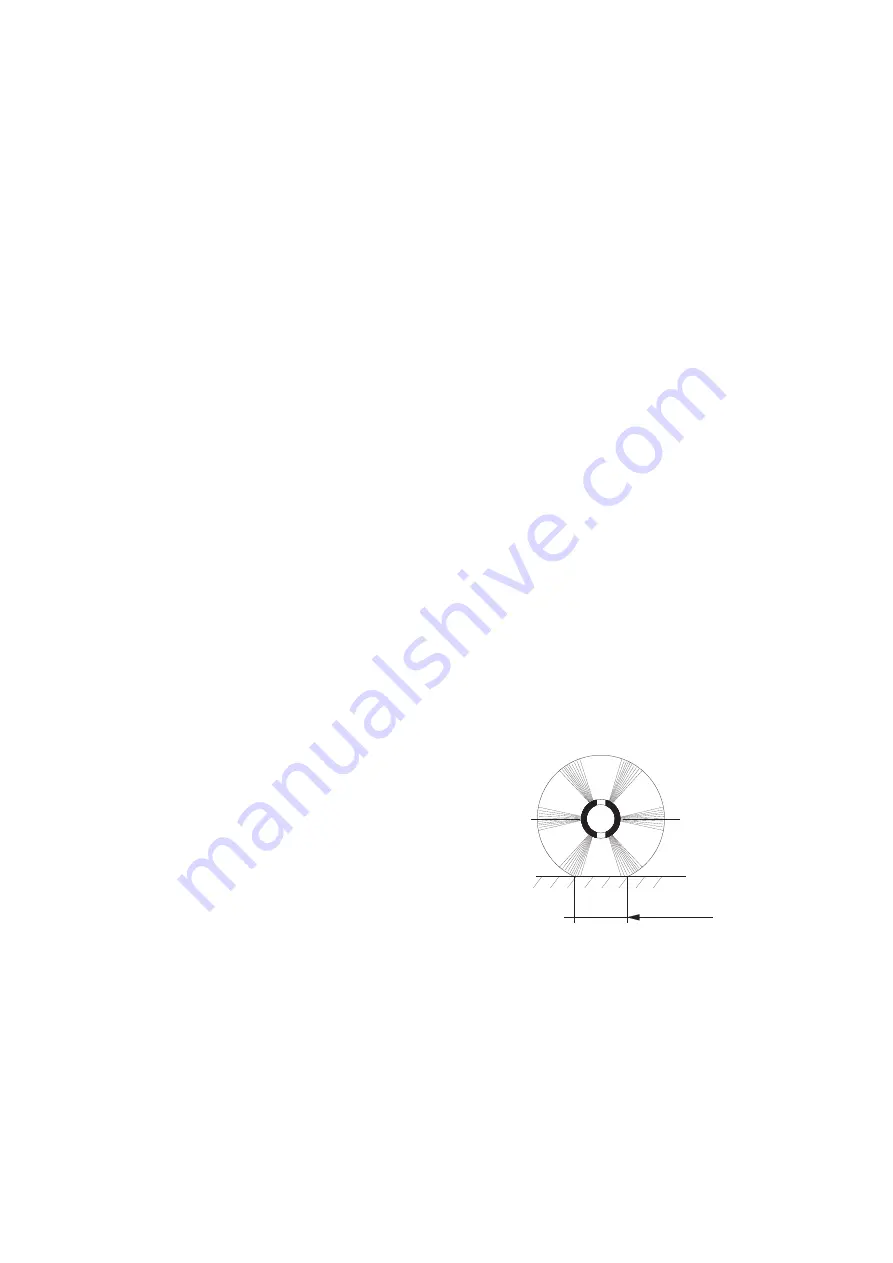
• ADJUST THE PRESSURE OF THE BRUSH IN ORDER THAT THE CLEAN PATH
DOESN’T GO OVER 55-60 MM (fig. 5)
REPLACEMENT OF MAIN BRUSH
• Remove the dirt container (fig.7 pos. A)
• Lift the front part of the machine up
• Remove the 2 blocking screws of the brush (fig. 7 pos. B))
• Remove and replace the main brush but pay attention to the bristles
(fig. 7 pos. C)
• Execute the adjustment in the way above mentioned
PERIODIC MAINTENANCE
55-60mm
FIG. 5
11
Summary of Contents for KOBRA EB
Page 2: ...2...


