29
5. Working with operating tools
WARNING
Operating a bevelling machine creates hot metal chips than jump away from the workpiece and the
machine. Wear appropriate clothing to protect yourself and do not operate the machine in explosive
atmosphere, such as in the presence of flammable liquids, gases or dust. Hot machine components,
hot metal chips and sparks may ignite the liquids, gases or dust.
Machine accuracy lays with a 1 mm limit (+ and -). Satisfactory results rely heavily on work piece
condition and preparation. Surfaces and edges of the workpiece must be even and free from slags or
welds. If present, they must be cleaned before operating EUROBOOR B60(S).
Unevenness and obstructions potentially cause personal harm, damage the machine, rapidly
decrease the lifetime of tools and do not benefit the operation.
It is advised to create work logs with all applied machine settings for future reference.
5.1 Bevelling plate material
1.
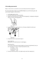
Prepare the machine as described in chapter 3
Angle adjustment:
Angle adjustment should be between 1 and 60 degrees
Depth adjustment:
It is strongly advised to have the depth adjustment not deeper than (additional) 6 mm per
pass. For example, if you want to create a bevel width of 15 mm:
First setting:
6 mm
Second setting:
12 mm
Third setting:
15 mm
2.
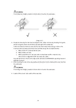
Position the machine vertically on the right (not left) side of the intended bevel
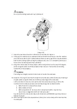
WARNING
Do not let the milling head touch any material yet!
3.
Adjust the machine and switch on the motor as described in chapter 4
4.
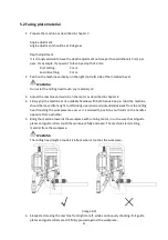
Firmly grip the machine at its available handles with both hands. Keep in mind the machine
should be moved from right to left during operation and potential kick-back from the milling
head touching the workpiece may occur. It is advised to position your hands on the handles
opposite from eachother.
5.
Bring the machine towards the workpiece with running motor, in such a way that all guide
plates and guide rollers touch the workpiece fully and even. The machine starts milling
material from the workpiece.
Summary of Contents for B60
Page 2: ...2 ...
Page 4: ...4 ...
Page 11: ...11 B60 B60S B60S shown image 1 1 image 1 2 ...
Page 12: ...12 B60 image 1 3 B60S image 1 4 ...
Page 20: ...20 image 2 3 ...
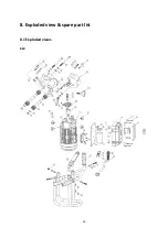
Page 39: ...39 8 Exploded view spare part list 8 1 Exploded views B60 ...
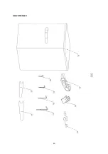
Page 40: ...40 B60 CONTINUED ...
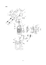
Page 41: ...41 B60S ...
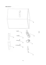
Page 42: ...42 B60S continued ...
Page 45: ...45 8 3 Wiring diagrams B60 ...
Page 46: ...46 B60S ...
Page 48: ...48 ...

