15
4. Using the machine
WARNING:
Always observe the safety instructions and applicable regulations.
WARNING:
To reduce the risk of serious personal injury, turn the machine off and disconnect
the machine from power source before making any adjustments or removing/installing
attachments or accessories.
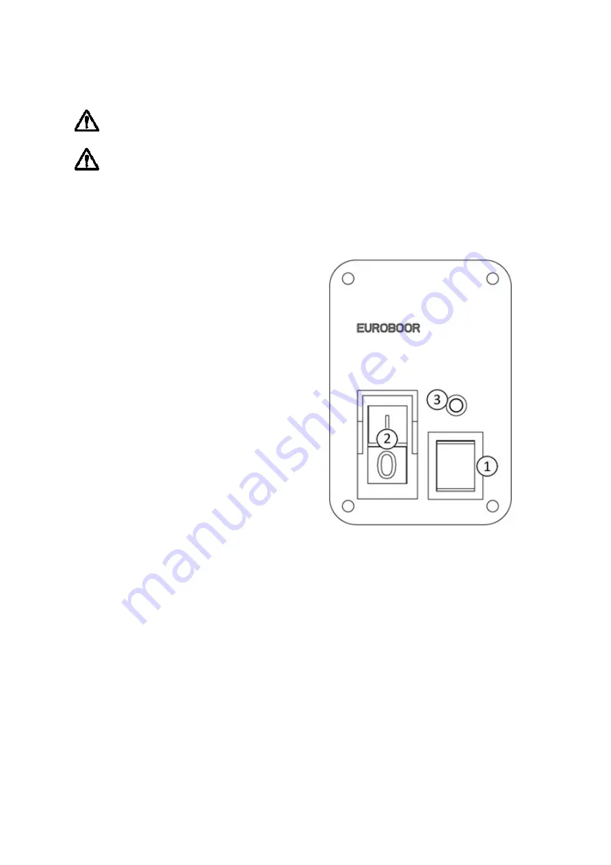
4.1 Control panel
The control panel on your magnetic drilling machine is designed for maximum ease of use and safety.
1.
Magnet switch
2.
Motor switch
3.
Magnet LED Indicator
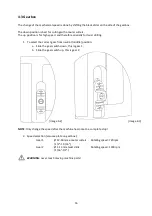
4.2 Spindle
This machine is equipped with a detachable spindle drive with 19.05 mm (3/4
")
Weldon connection.
To accommodate a drill chuck, either directly to the gearbox output shaft or with an adapter, the
spindle can be detached.
1.
Hold the gearbox output shaft in place with a narrow 18 mm (11/16") spanner;
2.
Loosen the spindle from the gearbox output shaft in counterclockwise direction with a 22
mm (7/8") spanner at the top of the spindle;
3.
Gently pull the spindle through the lubrication ring and spindle holder, while holding the ring
in place;
4.
You are now able to attach an adapter, drill chuck or different accessory to the gearbox
output shaft. The thread specification is 1/2
"
x 20 UNF.
To reattach the spindle, follow above steps in reverse order. Make sure all parts are correctly aligned
and firmly tightened.
[image 4-1]
Summary of Contents for ECO.40/2+
Page 27: ...27 8 Exploded views spare parts list 8 1 Exploded views...
Page 28: ...28...
Page 29: ...29...
Page 32: ...32 8 3 Wiring diagram...


