background image


22 

9880021100-CU 30P VERONA PRO 040413040413 


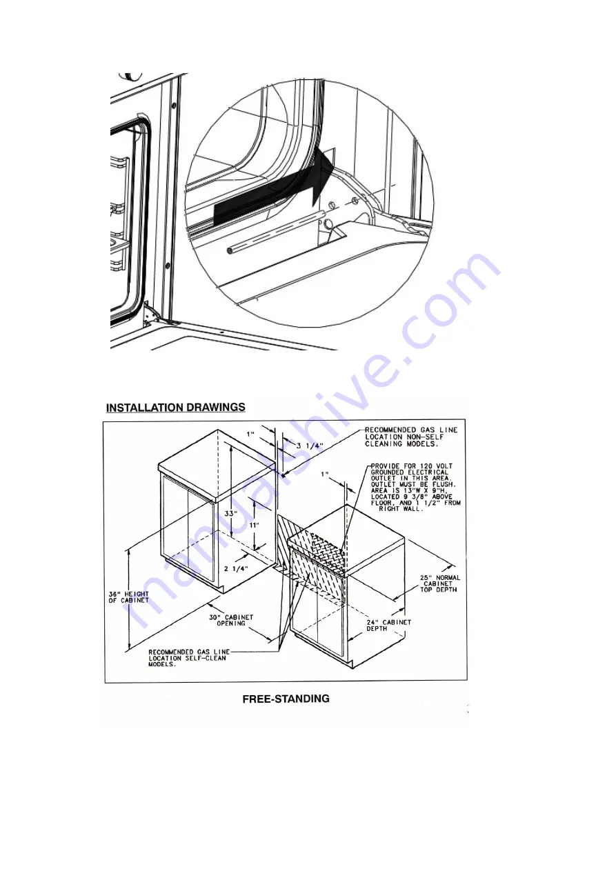
                                                                                                                                    Fig. n° 11 


Fig. n° 12 


Summary of Contents for verona pro VEFSGG30

Page 1: ...ance WARNING If the information in this manual is not followed exactly a fire or explosion may result causing property damage personal injury or death Do not store or use gasoline or other flammable vapours and liquids in the vicinity of this appliance WHAT TO DO IF YOU SMELL GAS Do not to light any appliance Do not touch any electrical switch Do not use any phone in your building Immediately call...

Page 2: ... frame sheet at the back area and verify that the anti tip device plate is properly engaged in the rear cover slot just above the frame sheet You should check this anytime the range has been moved Proper installation Be sure your appliance is properly installed and grounded by a qualified technician Never use your appliance for warming or heating the room Do Not leave children alone Children shoul...

Page 3: ...aluminium foil to line surface unit drip areas and oven bottoms Glazed cooking utensils Only certain types of glass glass ceramic ceramic earthenware or other glaze utensils are suitable for cooking range use without breaking due to the sudden change in temperature Utensils handles should be turned inward and not extended over adjacent surface units To reduce the risk of burns ignition of flammabl...

Page 4: ...ead Push in and turn the knob counterclockwise to the LIGHT HIGH setting After the burner lights turn the knob to the desired flame size fig 01 Caution When lighting the burner be sure all of the controls are in the OFF position Strike the match first and hold it in position before turning to knob to LIGHT HIGH For models with single action automatic ignition place a pan on the burner grate Push i...

Page 5: ... repair GAS BROIL BURNER USE Set thermostat to Broil mode by turning knob clockwise See fig 05 Follow oven gas burner ignition procedure paragraph Once broil burner is on allow a period of time for preheating the oven cavity before broiling food Attention use the Grill with the oven door open and for a maximum time of 15 minutes MINUTE MINDER Set required time by turning knob clockwise As the time...

Page 6: ... prior to supplying gas to the hob COOKWARE To achieve optimum surface cooking performance select heavy gauge flat smooth bottom pans that conform to the diameter of the cooking area as well as straight sides Pan size should match the size of the cooking area Pan should not extend more that 2 beyond the cooking area on gas cooking surface Proper pans will reduce cooking times use less energy and c...

Page 7: ...JUSTMENT chapter to adjust LOW setting if needed The flame should not extend beyond the edge of the pan fig 08B MAINTENANCE CLEANING SAFETY Turn off all controls and wait for appliance parts to cool before touching or cleaning them Do not touch the burner grates oven inner surface or surrounding areas until they have had sufficient time to cool Clean appliance with caution Use care to avoid steam ...

Page 8: ...painted or plastic surfaces ABNORMAL OPERATION Any of the following are considered to be abnormal operation and may require servicing Burner flame with yellow tips Sooty on pan bottom Difficult burner ignition Burners fail to remain lighted Burner will flame out Difficult on turning gas valves NOTES Control regularly the correct functioning of cooktop gas valves oven gas thermostat and selector sw...

Page 9: ...t on or stand on an open oven door This could cause the range to tip over break the door or injure the user Also do not attempt to open or close door or operate oven until door is properly replaced REPLACING THE OVEN LIGHT WARNING To prevent electrical shock and or personal injury 1 Before replacing the light bulb be sure the electric power is turned off at the circuit breaker 2 Do not operate the...

Page 10: ... cooktop For complete information in regard to the installation of wall cabinets above the range and clearances to combustible wall above the cooking top see the installation drawing fig n 12 and 13 For Safety Considerations do not install a range in any combustible cabinetry which is not in accord with the installation drawings NOTE 42 inch dimension between cooking top and wall cabinet shown on ...

Page 11: ...a well ventilated environment to guarantee a correct combustion gases exchange proper air circulation and working temperature within safety limits MODEL NUMBER PLATE The Model Number Plate is located on the underneath case A second Model Number Plate is applied on the front page of the instruction booklet ANTI TIP DEVICE INSTALLATION INSTRUCTIONS NOTE A risk of range tip over exists if the applian...

Page 12: ...two slots in the rear cover to choose from Also use a minimum of 2 screws to install bracket to the wall STEP 3 Range Installation A Align the range to its designated location and slide it back into position Make sure that the Anti Tip bracket plate is fully inserted into the range rear cover slot and above the lower frame plate B For Safety Considerations as well as optimum performance adjust the...

Page 13: ...OTE House wiring and fusing must comply with local codes If no local codes are applicable wire in accordance with the National Electrical Code ANSI NFPA 70 latest edition The three prong grounding plug offers protection against shock hazards DO NOT CUT OR REMOVE THE THIRD GROUNDING PRONG FROM THE POWER CORD PLUG If an ungrounded two hole or other type of electrical outlet is encountered it is the ...

Page 14: ...al block Connect new flexible cord prongs to terminal block and fix flexible cord lock remember earth wire yellow and green must be longer by one inch that the other ones For Line and Neutral wire connection follow signs on terminal block The flexible cord must be hold tight by the cord lock in such a way that it may not pulled out The flexible cord path must not be in proximity or in contact with...

Page 15: ...es water column Inlet pressure in excess of 14 in W C can damage the appliance pressure regulator or other gas components in this appliance and can result in a gas leak a A gas cut off valve should be put in an accessible location in the supply line ahead of the range for turning on and turning off gas supply If hob is to be connected to house piping with flexible or semi rigid metal connectors fo...

Page 16: ...This is to hold the burners in place on the burner base for shipping purposes only CHECKING PRESSURE OF HOUSE PIPING SYSTEM 1 The appliance and its individual shutoff valve must be disconnected from the gas supply piping system during any pressure testing of that system at test pressure in excess of lbs sq in 3 5 kPa or 13 8 in water column 2 The appliance must be isolated from the gas supply pipi...

Page 17: ...LIANCE PRESSURE REGULATOR CONVERSION The unit appliance pressure regulator must be set to match the type gas supply used If converting from natural gas to LP gas the appliance pressure regulator must be converted to regulate LP gas If converting from LP gas to natural gas the appliance pressure regulator must be converted to regulate natural gas To install the gas regulator you must you a CSA cert...

Page 18: ...NLY on the LOW setting Never adjust flame size on higher setting NOTE All gas adjustment should be done by a qualified service personnel only RANGETOP AND OVEN BURNER TECHNICAL DATA VEFSGG31SS NATURAL GAS MAX POWER BTU HR Injector Valve by pass BURNER Natural HIGH SMALL HIGH SMALL U POWER 18000 1 93 0 81 0 66 open 180 0 66 close POWER 14000 1 65 0 78 0 66 open 180 0 57 close OVEN 12000 1 60 0 40 o...

Page 19: ...cu ft 2 0 cu ft ENERGY POWER PERFORMANCE Consumption to reach 350 F Consumption to maintain 350 F for one hour Total consumption Consumption to reach 390 F Consumption to maintain 390 F for one hour Total consumption BROILING AREA OVEN ACCESSORIES One Dripping Tray Two Cooking Racks four rack positions DIMENSIONS OF THE APPLIANCES Series Width in Height in Depth in VEFSGG30SS 29 7 8 35 36 27 VEFSG...

Page 20: ...20 9880021100 CU 30P VERONA PRO 040413040413 FIGURES Fig n 01 Fig n 02 Fig n 03 Fig n 04 Fig n 05 Fig n 06 Fig n 07 ...

Page 21: ...21 9880021100 CU 30P VERONA PRO 040413040413 Fig n 08 Fig n 08A Fig n 08B BURNER CUP BURNER CROWN ORIFICE ELECTRODE BURNER BASE Fig n 09A Fig n 10 ...

Page 22: ...22 9880021100 CU 30P VERONA PRO 040413040413 Fig n 11 Fig n 12 ...

Page 23: ...23 9880021100 CU 30P VERONA PRO 040413040413 Fig n 13 Fig n 14 ...

Page 24: ...24 9880021100 CU 30P VERONA PRO 040413040413 Fig n 15 Fig n 16 ...

Page 25: ...25 9880021100 CU 30P VERONA PRO 040413040413 Fig n 17 Fig n 18 A Fig n 18 B Fig n 19 ...

Reviews: