background image


instruction and operation manual ZHK NANO 


34 / 116 

V04-18 


Attention:

 For soft bags the lower bags of the filter cells are to lift up in order to 

prevent damage with the clamping system (

Figure 60

)! 


Figure 60:

 Lifting the filter bags 


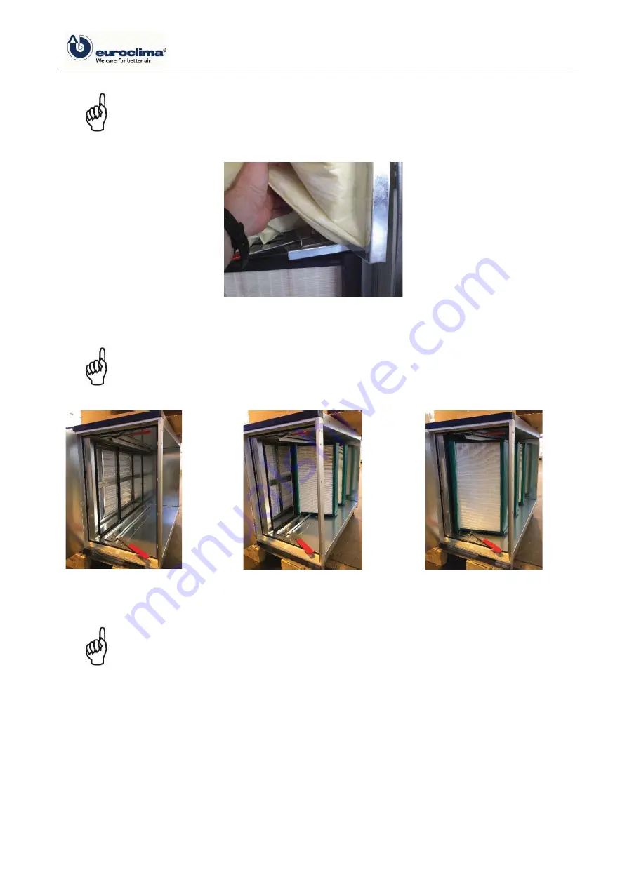
Attention: 

If different widths of filter are planned for one filter frame with clamp-

ing mechanism, then the order of the insertion have to be according the filter 
frame raster (see 

figure beneath

). Otherwise it leads to an air bypass.  


Figure 61:

 filter frame for different filter 

sizes 


Figure 62:

 consider the order accord-

ing the filter frame raster 


Figure 63:

 filter section with in-

serted filters 


Attention: 

Filters must be pushed completely to the back, so that all filters all 

around fit closely to the filter frame and an air bypass is avoided. For checking 
purposes, examine if the first filter fits closely to the sealing. (

Figure 65


Summary of Contents for ZHK NANO

Page 1: ...1 12 16758 7 21 0 18...

Page 2: ...guide subject specific standards as well as local national and international regulations must be observed Please give this instruction manual after com pletion of the work to the operating staff of t...

Page 3: ...n the order of the insertion have to be according the filter frame raster see figure beneath Otherwise it leads to an air bypass Figure 61 filter frame for different filter sizes Figure 62 consider th...

Page 4: ...nnection has to be ensured and the transmission of vibrations and longitudinal expansion between the device and the piping system must be safely prevented In order to avoid corrosion due to water the...

Page 5: ...the heat exchanger due to mechanical force a ring is used to reinforce the copper pipe Figure 67 and Figure 68 Figure 67 copper pipe with reinforcing ring Figure 68 copper pipe with inserted reinforc...

Page 6: ...ould be carried out as shown in the scheme Figure 72 with a three way valve as a mixing valve Compared with a flow control using a straight through valve this connection avoids unequal temperature pro...

Page 7: ...ral drains may not be connected to one siphon The water from the siphon must run in a funnel Before starting fill the siphon with water In case of outdoor units an antifreeze mechanism has to be provi...

Page 8: ...ball siphons with the below shown design are included in the delivery from EUROCLIMA then the following items should be observed during installation Depending on the suction side or pressure side moun...

Page 9: ...on suction side in direction of airflow before the fan Figure 78 Suction side execution Siphon on pressure side in direction of airflow after the fan The black plug must be removed for the pressure si...

Page 10: ...ed in the scope of supply has to be installed between the device housing and the component of the duct system The aero technical connections must be executed tension and torsion free i e no forces loa...

Page 11: ...0 915 1220 2 1372 5 1830 3 1982 5 2592 5 4 2745 3202 5 5 3355 3660 6 3812 5 3965 7 Figure 81 Information on the screw distance 6 3 1 Insulation of fresh air damper Before connecting the duct section...

Page 12: ...external protective earth system has to be executed according to EN 60204 1 pt 5 2 The minimum cross sectional surface of the earth at frequency converter has to be 10 mm otherwise 4 mm at units with...

Page 13: ...witch According to the standards IEC EN 60204 and VDE 0113 all hazardous facilities have to be equipped with a main switch which separates the plant from all active conductors of the main sup ply This...

Page 14: ...s type of control decreases the lifetime of the electric heater under circumstances significantly On Off at multistage electric heater Continuous e g with suitable thyristor control Fire risk With ele...

Page 15: ...east 5 min after cut off of electric heater By the use of an enabling contact see Figure 87 the control engineering also ensures that the electric heater can only start its operation when the fan is r...

Page 16: ...riggering temperature set to 70 C value must not be changed Sensor position downstream of electric heater in upper area of airflow Function alarm stop in case of over temperature because of missing ai...

Page 17: ...nt of the supply air volume flow 7 6 Lighting Depending on the number of delivered optional lamps the assignment of the switches and junction boxes can be found below 1 Lamp 1 switch 1 4 Lamp 1 switch...

Page 18: ...tools etc and documentation from the unit Such parts can be sucked in by the fan and lead to its destruction check all bolt connections and electrical connections and retighten if necessary Ensure th...

Page 19: ...d diff pressure Pa Sw Measured diff pressure Pa V Air density at the fan kg m If several fans in a fan section are operated in parallel with the same speed then the total airflow rate is accordingly a...

Reviews: