


Instruction Manual ZHK
48/129
V07-19.0
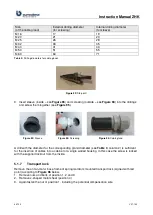
Size
(of the cable gland)
External drilling diameter
(for screwing)
Internal drilling diameter
(for sleeve)
M 16
17
19
M 20
21
23
M 25
26
28
M 32
33
35
M 40
41
43
M 50
51
55
M 63
64
71
Table 3:
Drilling diameters for cable glands
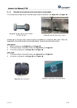
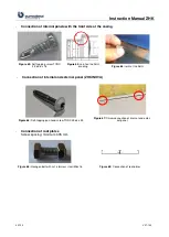
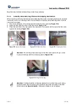
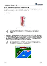
Figure 92:
Step drill
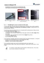
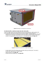
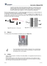
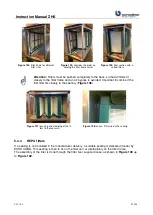
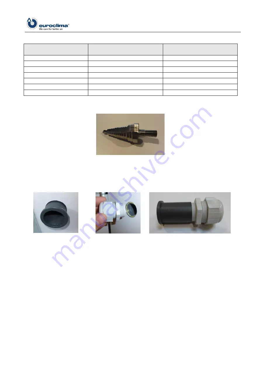
3. Insert sleeve (inside
–
) and screwing (outside
–
) into the drillings
Figure 93:
Sleeve
Figure 94:
Screwing
Figure 95:
Cable gland
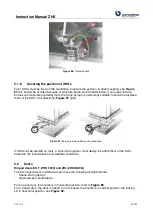
A drill with the diameter for the corresponding gland diameter (see
, column 2) is sufficient
for the insertion of cables into a cabinet or a single walled housing. In this case the screw is locked
with the supplied locknut from the inside.
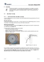
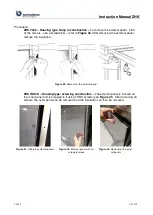
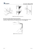
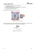
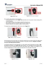
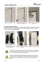
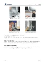
5.1.7
Transport lock
Remove the on fan-motor base frame of spring isolators mounted transport lock (signed with red
point) according to
below.
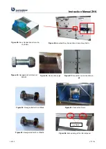
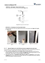
1. Remove nuts and bolts of position 1, 2 and 3
2. Remove z-shaped metal sheet (position 4)
3. Again fasten the nut of position 1, including the potential compensation wire
Summary of Contents for ZHK Series
Page 1: ...ZHK INSTRUCTION MANUAL ...


