


Instruction Manual ZHK
62/129
V07-19.0
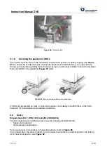
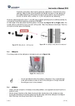
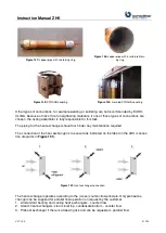
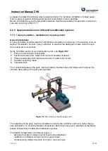
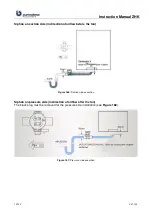
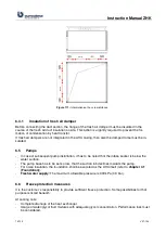
Hydraulic connection schemes of heating or cooling coil should be carried out as shown in the
scheme
with a three way valve as a mixing valve. Compared with a flow control using a
straight-through valve this connection avoids unequal temperature profiles, in that way air heating
or cooling is quite uniform along the coil surface.
Figure 152:
Hydraulic connection scheme
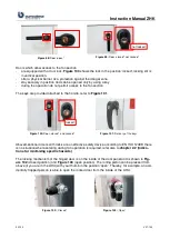
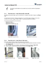
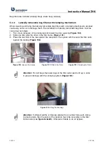
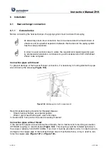
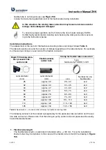
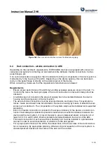
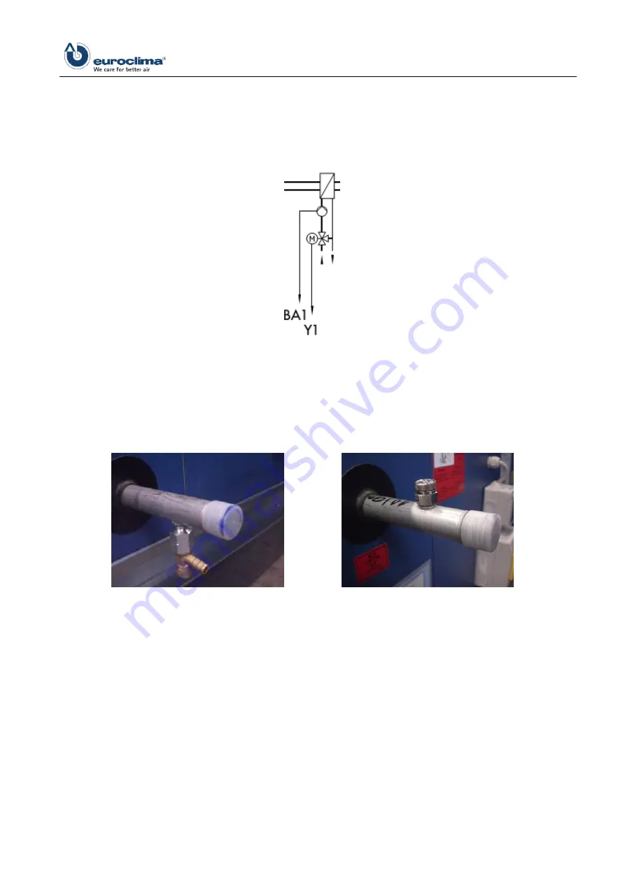
To vent and drain the heat exchanger connection, valves are mounted (on request). To ensure that
the correct operation is undertaken, it is important that the vent is on the highest point of the whole
water cycle and the drain at the lowest. Otherwise, the valves need to be mounted on another suit-
able point on the circuit.
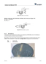
Figure 153:
Drain valve
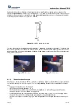
Figure 154:
Vent valve
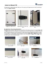
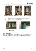
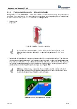
6.1.2
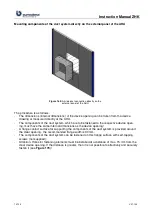
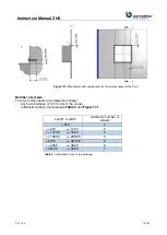
Steam heat exchanger
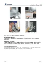
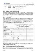
The heater is heated to above 70 °C, next to the heater are plastic parts which have been installed.
To prevent damage of the plastic parts, it is the responsibility of the client to undertake the follow-
ing:
-
Supply and installation of thermostat
-
thermostat trigger temperature: 70 °C
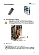
-
thermostat probe position: approx. 100 mm downstream of airflow through steam heat ex-
changer / approx. 100 mm below the top panel
-
A thermostat must be integrated into the AHU control system so that the steam supply valve
closes in the event of the temperature exceeding the trigger stated above.
-
function: interruption of steam supply at over-temperature for example because of missing air-
flow
Summary of Contents for ZHK Series
Page 1: ...ZHK INSTRUCTION MANUAL ...


