background image

Crisis EVC Network Expander Installation Guide

Page 10

www.eurofyre.co.uk

4.3  Cable and Wiring Guidance

4.3.1  Fire Telephone System

Any system using Type A outstations must use enhanced grade cabling throughout for all wiring, including the mains supply to the Crisis EVC 

Network Expander.

4.3.2  Disabled Refuge EVC System

For buildings less than 30m in height, or any building with sprinklers fitted, standard grade fire resistant cable may be used to wire Type B 

outstation and the mains supply to the Master Controller; as long as the planned evacuation will be completed in 30 minutes.

If the building is over 30m in height without sprinklers, or where the evacuation will take place over multiple stages exceeding 30 minutes, then 

enhanced grade cables must be used. 

4.3.3  Combined Systems

For systems containing Type A, Type B or Type C outstations, shared cable such as network cables must be enhanced grade.

Cabling to Type A or Type C outstations must be in enhanced grade fire resistant cabling. Individual spurs to Type B outstations can be wired in 

standard grade fire resistant cabling in accordance with the wiring guidelines already set out for disabled refuge systems.

4.3.4  “Assist Call” Emergency Assistance Alarm Systems

All installations must conform to Building Regulations Approved Document M.  The “Assist Call” is wired using 2 core cable, and the “Assist Call” 

plates can be wired in any order.

4.4  Cabling Methods

There are 3 cabling methods available:

 •

Connection to a Type A or Type C outstation: use 2 core enhanced grade fire resistant cable when extending a firefighting telephone system.

 •

Connection to a Type B outstation: use 2 core standard grade fire resistant cable when extending a disabled refuge system.

 •

Connection to an “Assist Call” system on a dedicated line requires 2 core 1mm CSA or above PVC sheathed.

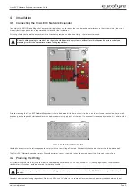
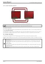
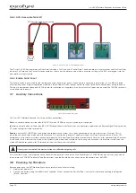
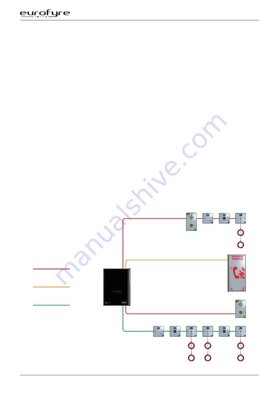
4.4.1  Crisis EVC Network Expander Wiring

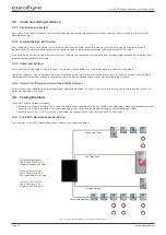
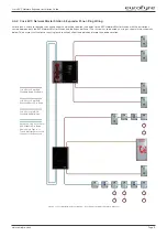
The wiring for a Crisis EVC Network Expander is shown in the schematic below.

1 off 2 Core 1.5mm CSA

Standard Rated Fire Cable

1 off 2 Core 1.5mm CSA

Enhanced Rated Fire Cable

1 off 2 Core 1mm CSA

Standard PVC Minimum

Accessible Toilet

Fire Telephone

Disabled Refuge

Accessible Bedroom

Figure 4:  Typical Wiring Diagram - Crisis EVC Network Expander

Summary of Contents for CRISIS

Page 1: ...EVC Network Expander Installation Guide Date July 2020 Document EF CRISISEVCNEIG Issue 1 0 www eurofyre co uk ...

Page 2: ...This page is intentionally left blank ...

Page 3: ...uipment damage Eurofyre is not responsible and cannot be held accountable for any liability that may arise due to improper use of the equipment and or failure to take proper precautions Only persons trained through an Eurofyre accredited training course can install test and maintain the system Liability You agree to install configure and use the products strictly in accordance with the Installatio...

Page 4: ...and purchasing of a Crisis EVC system It is assumed that anyone using this product has the knowledge and appropriate certification from local fire and electrical authorities Document Conventions The following typographic conventions are used in this document Convention Description Bold Used to denote Emphasis Italics Used to denote References to other parts of this document or other documents The ...

Page 5: ...ng 9 4 3 Cable and Wiring Guidance 10 4 4 Cabling Methods 10 4 5 Battery Information 12 4 6 Outstation Connections 13 4 7 Auxiliary Connections 14 4 8 Powering Up Procedure 14 4 9 Powering Down Procedure 14 5 Hardware Configuration Procedure 15 5 1 Network Expander Exchange PCB Dipswitch Settings 16 6 Indications 17 6 1 Mode Indicator Summary 17 6 2 Power Supply CPU indicator Summary 18 6 3 Zone I...

Page 6: ...ired i e fire control rooms and building reception These additional EVC Network Master Stations have the facility to filter the information that is displayed so if there are several buildings with a EVC Network Master Station in each building the EVC Network Master Station can be configured to only display answer EVCS calls from that building The system also has the ability for all calls to be dis...

Page 7: ...nder Panel requires a 3A spur returning to a breaker clearly marked EVCS DO NOT TURN OFF If the Crisis EVC Network Master Station and the Crisis EVC Network Expander are distributed around a site it is essential that both Crisis Stations are on the same mains phase as they are classified TEN 230V Powering from different phases can mean a 440V potential can be present in a Crisis EVC Station during...

Page 8: ...lation Guide Figure 1 Crisis EVC Network Expander Front Use the 2 5mm AF Hex Key supplied to open the right hand front cover Verify the following items are present 4 x Line Cards 1 x 3 way Mains Connector 1 x 2 way Fault Connector 1 x 2 way In Use Connector 1 x 2 way Enable Connector 4 x 2 way Network Connectors 1 x Battery Lead If there are any items missing please contact your supplier or Eurofy...

Page 9: ...2 slotted entries with a dedicated mains supply entry at the rear If a knockout is removed by mistake fill the hole with a good quality cable gland Net IN A B Net IN C D Net OUT A B Net OUT C D Line 1 Line 2 Line 3 Line 4 Line 5 Line 6 Line 7 Line 8 Mains Fault Enable Figure 3 Crisis EVC Network Expander Top Entries Unused knockouts must be left unopened to comply with the Low Voltage Directive Ac...

Page 10: ...dual spurs to Type B outstations can be wired in standard grade fire resistant cabling in accordance with the wiring guidelines already set out for disabled refuge systems 4 3 4 Assist Call Emergency Assistance Alarm Systems All installations must conform to Building Regulations Approved Document M The Assist Call is wired using 2 core cable and the Assist Call plates can be wired in any order 4 4...

Page 11: ...Expander Panel The system has to be wired as a ring as shown in the schematic below This ensures that the loss of any single cable will not affect the operation of more than one outstation 1 off 2 Core 1 5mm CSA Standard Rated Fire Cable 1 off 2 Core 1 5mm CSA Enhanced Rated Fire Cable 1 off 2 Core 1mm CSA Standard PVC Minimum Network 2 off 2 Core 1 5mm CSA Standard Fire Rated Cable unless Type A ...

Page 12: ...Station during a major fault incident 4 5 Battery Information In the event of mains failure BS5839 Part 9 2011 requires battery backup for 24 hours standby and 3 hours operation thereafter A Crisis EVC Network Expander requires one number 12V 7AH vent regulated sealed lead acid battery The battery is not supplied with the Master Station Safety Information Sealed Lead Acid batteries contain sulphur...

Page 13: ... connected to the end of line terminal in the outstation For Jack points and the Assist Call system the end of line 10kΩ resistor should also be removed from the accessory pack and connected to the last plate on the system 4 6 1 Type A Outstation Line Card in Master Station EOL resistor fitted if Line unused Figure 7 Type A Outstation Wiring Diagram The Earth screen should be sleeved and connected...

Page 14: ...n Use is a normally open volt free relay 30V DC 1A connection which closes when any outstation is operated see Remote Signal Display section 7 7 switch settings for further information Enable is a normally CLOSED input and is required to operate the system this is often connected to the fire alarm system If Jumper J9 is in place then no connection is required at the terminals This function only di...

Page 15: ...ue to the ability for outstations to be wired from any panel therefore there is no loss of functionality due to cable faults as a ring provides redundancy Network connections used are Network Out and Network In with Network In on one Station wired to Network Out on the other Station A to A B to B C to C and D to D The default network address setting for the Crisis Network Expander is 2 When adding...

Page 16: ...FF ON OFF ON ON 43 OFF OFF ON OFF ON OFF 12 ON ON OFF OFF ON ON 44 ON ON OFF OFF ON OFF 13 OFF ON OFF OFF ON ON 45 OFF ON OFF OFF ON OFF 14 ON OFF OFF OFF ON ON 46 ON OFF OFF OFF ON OFF 15 OFF OFF OFF OFF ON ON 47 OFF OFF OFF OFF ON OFF 16 ON ON ON ON OFF ON 48 ON ON ON ON OFF OFF 17 OFF ON ON ON OFF ON 49 OFF ON ON ON OFF OFF 18 ON OFF ON ON OFF ON 50 ON OFF ON ON OFF OFF 19 OFF OFF ON ON OFF ON ...

Page 17: ...Indications Figure 11 Crisis EVC Network Expander Indication 6 1 Mode Indicator Summary Mode Description Green Solid Normal state Red Solid Outstation off hook Blue Solid Assist call active Yellow Solid Type B disable function active Enable jumper open Table 2 Indicator Summary ...

Page 18: ...he master station when accepted the LED goes solid 6 3 Zone Indicator Summary Zone Indicator Status Description Slow Flashing Red Outgoing call Fast Flashing Red Incoming call from type A outstation Normal Flashing Red Incoming call from type B outstation Normal Flashing Green Call connected to local master handset Normal Flashing Green Red Call on hold Solid Yellow Line Short circuited Slow Flash...

Page 19: ...vice missing or network faults are reported address these before continuing Once remedied re upload the site configuration to ensure all panels are programmed Lift the master handset receiver and listen for a cadence tone All outstations may be tested now visit each outstation in turn and test that it is connected to the correct Master Station or Expander panel and perform an intelligibility test ...

Page 20: ...Crisis EVC Network Expander Installation Guide Page 20 www eurofyre co uk Notes ...

Page 21: ...mA 500mA Table 4 Power Supply Charger Technical Specification Inputs Lines 8 Remote Enable Short to Use End of Line Monitoring 10KΩ 0 6W Resistor Table 5 Inputs Technical Specification Relay Outputs Number and Type Fault and In Use Volt Free 30Vdc 1A Table 6 Relay Outputs Technical Specification Controls Number and Type None Table 7 Controls Technical Specification Indication Number and Type 3 x P...

Page 22: ...This page is intentionally left blank ...

Page 23: ...This page is intentionally left blank ...

Page 24: ...Back Page ...

Reviews: