


Crisis EVC Network Expander Installation Guide
Page 15
www.eurofyre.co.uk
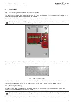
4.9 Powering Down Procedure
To power down the Crisis EVC Network Expander:
1.
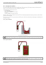
Disconnect the battery. Always disconnect the Negative (Black - ) terminal first, before disconnecting the Positive (Red + ) terminal.
2. Remove mains power.
5 Hardware Configuration Procedure
The Crisis range of panels has in-built networking. This is described in the product overview section. Install the additional panel/station as per the
relevant parts in the installation section 4.
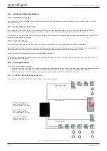
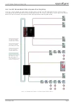
Any panels on the network must be wired as a ring (see 4.4.1 and 4.4.2). This is due to the ability for outstations to be wired from any panel
therefore there is no loss of functionality due to cable faults as a ring provides redundancy.
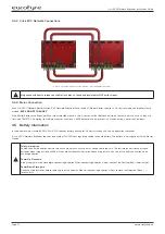
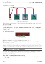
Network connections used are Network Out and Network In, with Network In on one Station wired to Network Out on the other Station (A to A, B
to B, C to C, and D to D).
The default network address setting for the Crisis Network Expander is 2.
When adding a Network Expander, it must have a unique network address, and must be included in the site configuration file (see section 6 of the
Crisis EVC Network Master Station Installation Guide).
If the site configuration is not updated the panel will not be seen by the rest of the network and importantly any outstations connected to that
panel will not operate as they will not be seen by the rest of the network.