


Crisis EVC Network Expander Installation Guide
Page 19
www.eurofyre.co.uk
7 Commissioning Procedure
•
The commissioning should be carried out by a competent person who has a basic knowledge and understanding of the design and
installation sections of BS5839-9:2011, and has access to the specification of the project.
•
The 500v insulation tests should have been carried out by the installer and the results made available to the commissioning engineer.
•
All cables should be correctly labelled.
•
Test field wiring and check for end-of-line 10KΩ resistor. Check cables are clear from any short or open circuits.
•
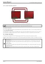
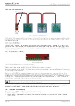
Connect outstation cables into Line Cards ensuring the Earth is sleeved and terminated into the Earth block.
•
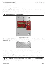
Configure relevant dipswitches for the network settings that may be required as per the set up section in this manual.
•
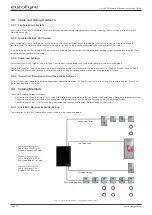
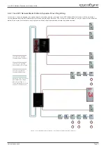
Connect the network cabling (if appropriate), ensuring Net OUT ABCD is correctly connected to Net IN ABCD and the ring is continuous.
Only Connect the Earth screen of the Net IN cables.
•
Power up the Crisis EVC Network Expander using mains only, fed from a 3A fuse fitted in an unswitched fused spur. The AC power indicator
will be illuminated, and the DC power indicator is extinguished. The PSU fault and General fault indicators will be illuminated. There should
be no line fault indicators illuminated.
•
If there are no line faults present, the battery may be connected. The DC power indicator will be illuminated, and the PSU fault and General
fault indicators are extinguished when battery is connected.
•
If there are any line fault indicators illuminated, then the field wiring should be checked prior to the battery being connected.
•
Repeat the power up section for any additional Expander panels or additional EVC Master Stations.
•
Upload the site configuration from the Micro SD Card (recommended) or using the menus.
•
If device missing or network faults are reported address these before continuing. Once remedied re-upload the site configuration to ensure
all panels are programmed.
•
Lift the master handset receiver and listen for a cadence tone.
•
All outstations may be tested now, visit each outstation in turn and test that it is connected to the correct Master Station or Expander panel
and perform an intelligibility test. This test should be conducted when the building has normal background noise levels. The intelligibility test
requires two personnel.
•
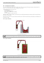
Where Assist Call is fitted, all pull cords in each circuit should be tested, acknowledged at the panel, cancelled at the call location and the
panel text checked. Ensure all controls and indicators operate correctly.
•
When all outstation tests are complete, network cable checks should be performed to ascertain correct operation by unplugging network
cable to ensure the network is correctly fault monitoring and continues to work with a single cable fault.
•
When complete the log may be retrieved from Micro SD Card, saved as a spreadsheet and kept for record purposes.
8 Maintenance
It is a requirement of BS 5839-9:2011 that a maintenance agreement be in place for the EVCS. The maintenance schedule should be as follows:
Frequency
Test
Weekly
Test a different outstation on the system each week and make a call to the control. Repeat each week until all outstations and
master stations are tested. Record these results in the site log. *If more than one master station is present alternate weekly.
Biannually
Engineer call to check system operation, intelligibility, field strength of attached AFILS equipment and check battery health.
Record results and any variations into the site Log Book
Yearly
Engineer call to check system operation perform 100% outstation and master station operation, field strength of attached AFILS
equipment and check battery health. Record results and any variations into the site Log Book
5 Yearly
In addition to Yearly tests replace all batteries and record in Log Book.
Table 39: Maintenance


