Crisis EVC Network Expander Installation Guide
Page 9
www.eurofyre.co.uk
4 Installation
4.1 Connecting the Crisis EVC Network Expander
To comply with EMC (Electro Magnetic Compatibility) regulations and to reduce the risk of electrical interference in the system wiring, the use of
fire-resistant screened cables is recommended throughout the installation.
All wiring should come into the enclosure via the knockouts provided, and be fixed tidily to the relevant terminals.
Correct cable glanding is essential. Due regard should be paid to any system specifications which demand a certain cable type,
providing it meets the appropriate national wiring regulations.
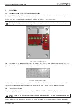
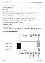
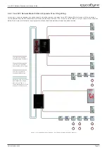
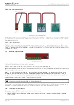
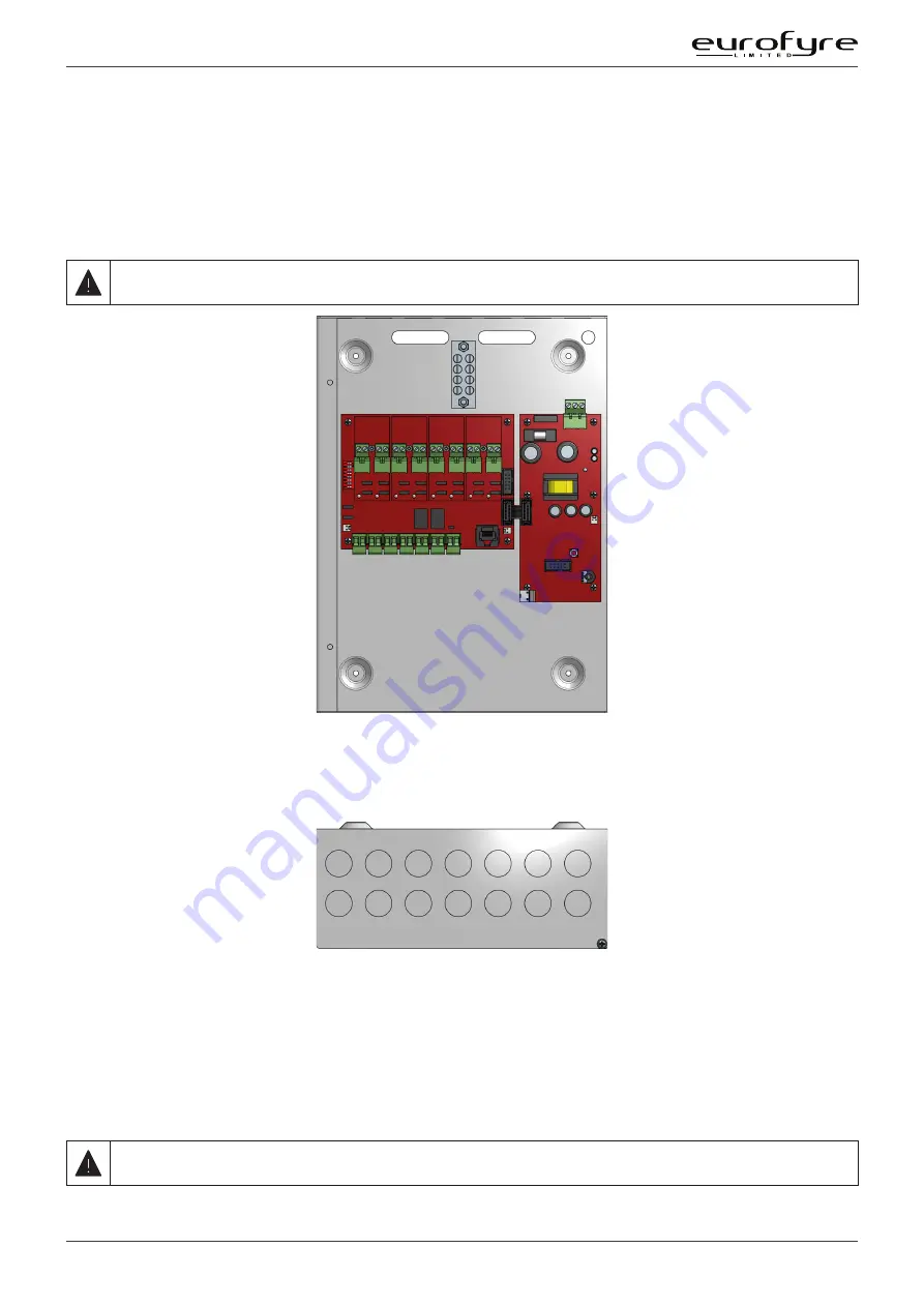
Figure 2: Crisis EVC Network Expander Internals
Prior to mounting the Crisis EVC Network Expander, it should be decided if the field wiring is to be run on the surface or concealed. There are 14
knockouts on the top and 2 slotted entries with a dedicated mains supply entry at the rear. If a knockout is removed by mistake, fill the hole with a
good quality cable gland.
Net IN
A + B
Net IN
C + D
Net OUT
A + B
Net OUT
C + D
Line 1
Line 2
Line 3
Line 4
Line 5
Line 6
Line 7
Line 8
Mains
Fault/
Enable
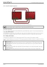
Figure 3: Crisis EVC Network Expander Top Entries
Unused knockouts must be left unopened to comply with the Low Voltage Directive. Accidentally knocked out holes should be blanked off.
The Crisis EVC Network Expander weighs 5kg with batteries, so care should be taken to securely mount the Station on stud walling.
4.2 Planning the Wiring
All system wiring should be installed to meet the appropriate parts of BS5839 Part 9:2011 and BS 7671 (Wiring Regulations). Other national
standards of installation should be adhered to where applicable.
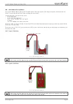
Do not test wiring using an insulation tester (Megger) with any equipment connected, as the 500 Volt test voltage will destroy these
devices.
You must observe local wiring regulations. Do not run SELV and LV cables in the same enclosure without adequate insulation between them.


