Crisis EVC Network Expander Installation Guide
Page 12
www.eurofyre.co.uk
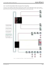
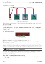
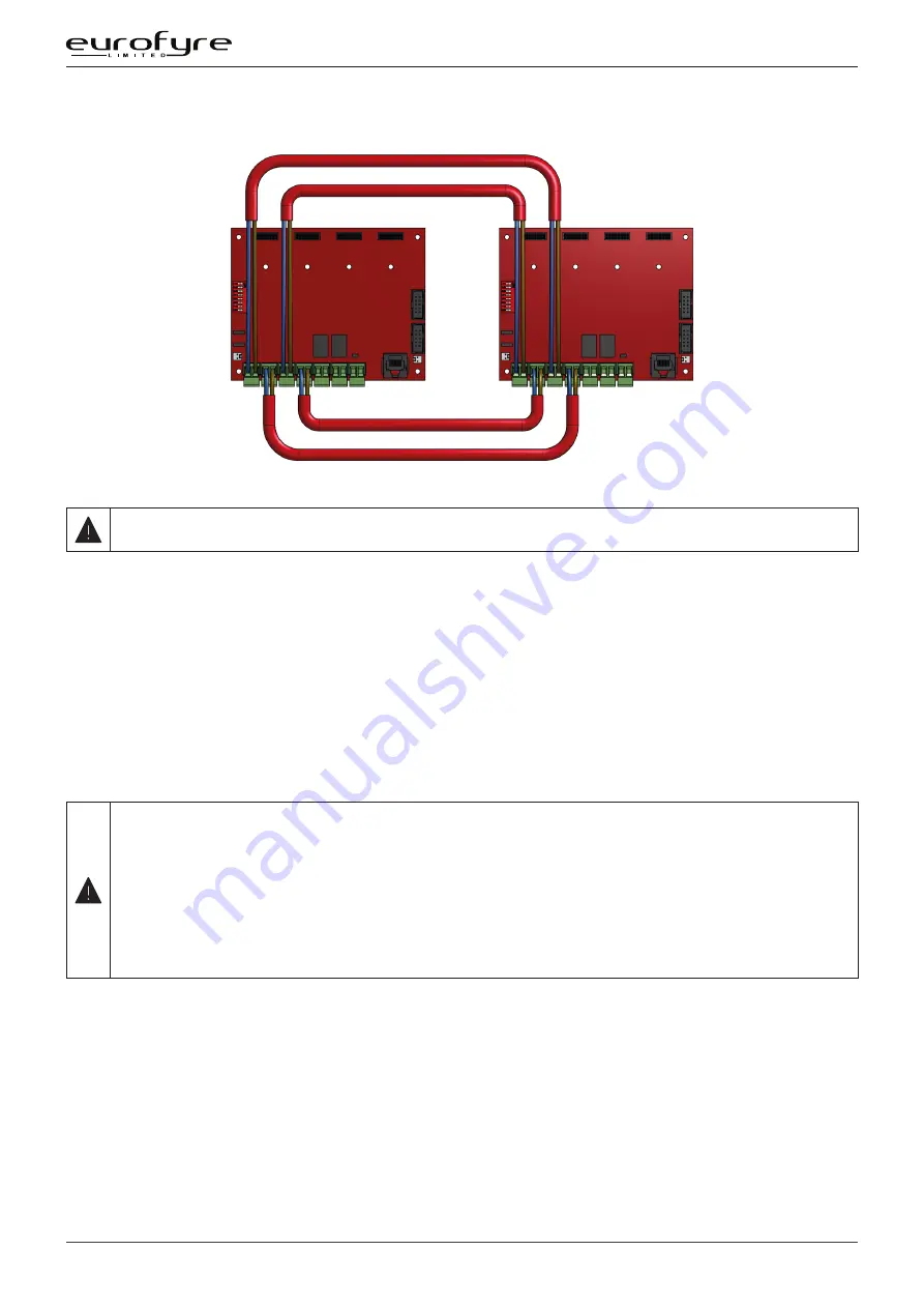
4.4.3 Crisis EVC Network Connections
A B
C D
A B
C D
A B
C D
A B
C D
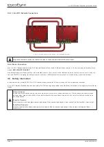
Figure 6: Typical Network Connection Diagram - Crisis EVC Network Expander
Only connect the earth screens on the Net in cables, cut back and insulate Net OUT earth screens.
4.4.4 Mains Connection
Each Crisis EVC Network Master Station, EVC Network Expander Panel and EVC Master Station requires a 3A spur, returning to a breaker clearly
marked “
EVCS DO NOT TURN OFF
”.
If the Master Stations and Expander Panel are distributed around a site, it is essential that both panels are on the same mains phase, as they are
classified TEN 230V. Powering from different phases can mean a 440V potential can be present in a Station during a major fault incident.
4.5 Battery Information
In the event of mains failure BS5839 Part 9:2011 requires battery backup for 24 hours standby and 3 hours operation thereafter.
A Crisis EVC Network Expander requires one number 12V 7AH vent regulated sealed lead acid battery. The battery is not supplied with the Master
Station.
Safety Information:
Sealed Lead Acid batteries contain sulphuric acid which can cause burns if exposed to the skin. The low internal resistance of these
batteries mean large currents will flow if they are accidentally short-circuited causing burns and a risk of fire. Exercise caution when
handling batteries.
Power Up Procedure:
Always apply mains power before connecting batteries. When connecting batteries, always connect the Positive (Red +) terminal first.
Power Down Procedure
Disconnect the batteries before removing the mains power. When disconnecting batteries, always remove the Negative (Black – )
terminal first.


