


Crisis EVC Network Expander Installation Guide
Page 13
www.eurofyre.co.uk
4.6 Outstation Connections
The Crisis EVC Network Master Station and EVC Network Expander Panel are configured via the configuration spreadsheet contained on the
Micro SD Card supplied with the Master Station, for configuration see section 6.
The following devices are available on the system:
•
Type A (fixed phone)
•
Type B (hands-free refuge point)
•
Type C “Combi” (combined Type A and Type B)
•
Jack Point
•
“Assist Call” emergency assistance alarm system
For Type A, Type B, and Type C outstations, the end-of-line 10kΩ resistor should be removed from the accessory pack and connected to the end-
of-line terminal in the outstation.
For Jack points and the “Assist Call” system, the end-of-line 10kΩ resistor should also be removed from the accessory pack and connected to the
last plate on the system.
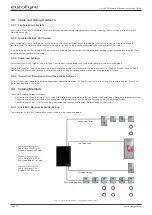
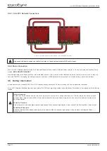
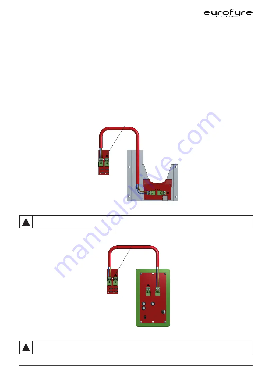
4.6.1 Type A Outstation
Line Card
in Master
Station
EOL resistor fitted if Line unused
Figure 7: Type A Outstation Wiring Diagram
The Earth screen should be sleeved and connected to the terminal block in the controller, and the earth stud in the Type A outstation.
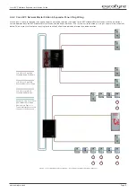
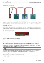
4.6.2 Type B Outstation
Line Card
in Master
Station
EOL resistor fitted if Line unused
Figure 8: Type B Outstation Wiring Diagram
The Earth screen should be sleeved and connected to the terminal block in the controller, and the earth connection in the metal back
box (if a plastic back-box is used cut the earth back and insulate at the outstation).


