Crisis EVC Network Expander Installation Guide
Page 14
www.eurofyre.co.uk
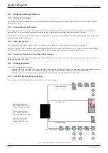
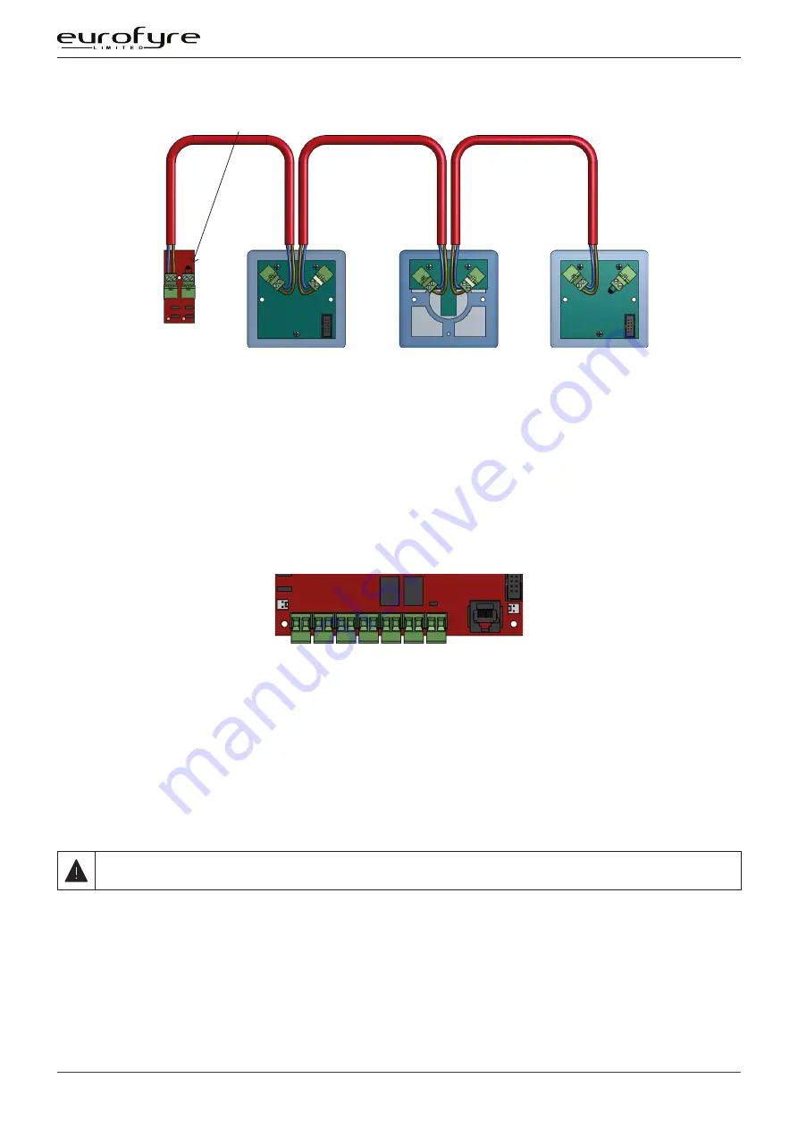
4.6.3 ACA Accessible Toilet Kit
Line Card
in Master
Station
EOL resistor fitted if Line unused
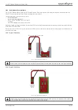
Figure 9: ACA Accessible Toilet Kit Wiring Diagram
The “Assist Call” ACA kit comprises an Over Door Indicator, a Pull Cord, and a Cancel Plate. The above order is a typical order; with the Over Door
Indicator, Pull Cord and the Cancel Plate connected as shown, but the plates can be wired in any order as long as the EOL resistor goes into the
free terminal of the last plate.
4.6.4 Enable Switch Input
The Enable Switch Input is used for the remote enabling or disabling of panels, it connects to a spare line input in either a Crisis Master Station
or System Expander. A typical application would be a sports stadium which requires control to switch to the match control room during the event.
The input is monitored and expects a 470R resistor for activation, not supplied (a fire alarm manual call point may be used) The 10K EOL resistor is
as supplied with the panel.
4.7 Auxiliary Connections
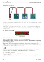
Figure 10: Auxiliary Connections
The Crisis EVC Network Expander has three auxiliary connections:
Fault
is a normally closed volt free relay (30V DC 1A) which OPENS on any fault, including loss of power.
In Use
is a normally open volt free relay (30V DC 1A) connection which closes when any outstation is operated, see Remote Signal Display section
7.7 switch settings for further information.
Enable
is a normally CLOSED input and is required to operate the system, this is often connected to the fire alarm system. If Jumper J9 is in
place, then no connection is required at the terminals. This function only disables Type B outstations, with Type A outstations and “Assist Call”
emergency assistance alarm systems continuing to operate. Calls from Type B outstations automatically “time out” after approximately 30 minutes.
It is advised that this feature is not used as the system should always be available, not just during an evacuation. If the feature is used, then the
mode LED illuminates yellow after 30 seconds to show that the system is disabled.
If the system is disabled, the master station can still make outgoing calls.
If this function is used, it only requires connection with one panel on the network. If the Enable Input is CLOSED on one panel, then all panels on
the network are CLOSED. To disable Type B outstations, then the Enable Input on all panels on the network must be OPEN.
4.8 Powering Up Procedure
Before powering up the EVC Network Expander, carefully check all internal wiring.
1.
Apply mains power first.
2. Connect the battery using the battery leads supplied. Always connect the Positive (Red + ) terminal first before connecting the Negative
(Black - ) terminal.


