background image

ProFyre C8 User & Maintenance Guide + Log Book

Page 6

www.eurofyre.co.uk

1  Fire Alarm Control Panel Safety Issues 

There is no need to open this fire alarm during normal operation. Any work carried out on this system must be performed by a competent person 
who is familiar with this type of system.

This equipment will operate safely provided it has been installed correctly in compliance with the Installation Manual.

It is recommended that the system is serviced frequently. It is customary to arrange a regular maintenance contract with a competent organisation. 
(Ask the installation company for recommendations). The system needs a thorough maintenance check annually at the very minimum.

If any part of this Fire Alarm Control Panel becomes damaged, contact the company responsible for system maintenance to arrange repair/
replacement.

European Union Directives Conformance Statement

This product has been manufactured in conformance with the requirements of all applicable EU Council Directives. The Declaration of 
Conformance for this product is located at the following Address: Eurofyre Limited, Unit C1 Knowle Village Business Park, Mayles Park, 
Wickham, Hampshire, PO17 5DY, United Kingdom. 

2  The Purpose of a Fire Alarm System 

1. 

A fire alarm system is used to provide an early warning of a fire, so that the property can be evacuated and the fire extinguished if it can be 
safely tackled, or the local fire brigade called, according to the company evacuation procedure. 

2.  An alarm can be raised from smoke and heat detectors, or manually by a person operating a manual call point. 
3. 

To split the building into zones, each covering a different area of the building. This will indicate which area of the system is giving the alarm 
(or fault). 

4. 

To start the sounders, and indicate which zone (area of the building) has signalled the fire. It will also activate its auxiliary relay. 

2.1  Fault Monitoring

All circuits must be checked for line integrity. If a part of the system has a problem which may affect its operation, a fault warning must be given by 
the fire alarm panel (LED & buzzer indication). The fault relay will also activate.

2.2 Disablements

An engineer may be required to work on part of a system, while the system is still active (e.g. extending a detection zone). During such 
circumstances, it would be advisable to disable that zone, so that it will not give false alarms. Similarly you may wish to disable a zone that has 
a fault that has not been fixed, or a zone covering an area with a temporary unusual environment, such as an area which is dusty because of 
construction work etc.

2.3 Delays

In public places, it may be desirable to delay the activation of an alarm until the responsible person has verified the cause of the alarm. (This would 
avoid a panic evacuation caused by a smoky room, or a maliciously activated call point.) On verification of the alarm, the sounders can be started 
by pressing the override button, or the panel can be reset in the case of a false alarm. If a delay has been set, it must be recorded on the system 
configuration chart at the back of this manual.

2.4  Power Supply Equipment - General Description

The Profyre C8 FACP has an integral linear power supply capable of supplying 1.2 amps in total. It contains a current limited output for charging 
sealed lead acid batteries (7.0Ah maximum). The PSE is monitored for main supply failure, the battery not taking a charge, low battery voltage 
and resistance. If the battery voltage drops below approximately 20VDC (a fault condition), the battery charging current will be turned off, thus 
stopping charging. This PSE is only capable of supplying power to the CIE, and is not designed for any other use.

Summary of Contents for ProFyre C8

Page 1: ...ProFyre C8 User Maintenance Guide Log Book Date April 2019 Document EF C8UG Issue 2 0 www eurofyre co uk ...

Page 2: ...This page is intentionally left blank ...

Page 3: ...se equipment damage Eurofyre is not responsible and cannot be held accountable for any liability that may arise due to improper use of the equipment and or failure to take proper precautions Only persons trained through an Eurofyre accredited training course can install test and maintain the system Liability You agree to install configure and use the products strictly in accordance with the User M...

Page 4: ...enote Emphasis Italics Used to denote References to other parts of this document or other documents The following icons are used in this document Convention Description Recommended guideline Advising to do so Caution Not appropriate to do so or care taken to avoid danger or mistakes Contact Us Telephone 44 0 1329 835 024 Email sales eurofyre co uk technical eurofyre co uk Website www eurofyre co u...

Page 5: ...ounders 15 8 3 To Enable a Zone and or External Sounders 15 9 Sounder Delays 16 9 1 What is a Sounder Delay 16 9 2 Sounder Delay Setting 16 9 3 How the Panel Indicates Sounder Delay 16 9 4 A Fire Alarm Condition on a Delayed Panel 16 9 5 Overriding a Delay in the Event of a Genuine Fire Alarm 16 9 6 Reset the System in the Event of a False Alarm 16 9 7 To Turn Off the Sounder Delay 16 10 Zone Test...

Page 6: ...lt 4 To start the sounders and indicate which zone area of the building has signalled the fire It will also activate its auxiliary relay 2 1 Fault Monitoring All circuits must be checked for line integrity If a part of the system has a problem which may affect its operation a fault warning must be given by the fire alarm panel LED buzzer indication The fault relay will also activate 2 2 Disablemen...

Page 7: ...ll the applicable Directives including the CPR EMC and the Low Voltage Directive LVD Please refer to Kitemark certificate KM 631788 and Certificate of Constancy or Performance 0086 CPR 644893 for further information EN54 2 1997 A1 2006 Fire detection and fire alarm systems Control and indicating equipment EN54 4 1997 A1 2002 A2 2006 Fire detection and fire alarm systems Power supply equipment 0086...

Page 8: ...nt elements held on site 47 2 j 1 2 11 In the event of a pre alarm determine the cause take appropriate action pre determined fire routine if the cause is the start of a fire arrange maintenance if the cause is a contaminated detector head 47 3 With the ProFyre C8 fire alarm panel we recommend the following tests are carried out Daily Inspection Check that the green power LED is lit If there are a...

Page 9: ...tate To put the panel into the accessed state Enter the access code 1245 then press To exit accessed state press three times If the wrong code is entered three times then the LED display will light a combination of LED s If this happens you will need to contact Eurofyre Limited for the code Changing the access code 1 Enter the current access code and press Control Enable lit 2 Press for 3 seconds ...

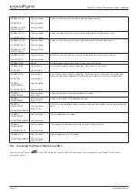
Page 10: ...ISABLEMENT SOUNDER DELAY Constant Red Constant Red Constant Yellow Constant Yellow A fire has occurred in the zone indicated The sounders have a delay set and will become active after the programmed delay To override the display press override sounder delay GENERAL DISABLEMENT Flashing Yellow Fast 4hz The panel is ready for selecting disable or test mode GENERAL DISABLEMENT Flashing Yellow Slow 0 ...

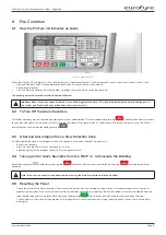
Page 11: ...in active The Panels internal buzzer can also be silenced by pressing 6 3 A Second Alarm Signal from a New Detection Zone If another detection zone is activated after the alarm sounders have been silenced the panel will Restart the sounders Light the zone fire LED s for any new zone s in alarm Keep the light s for the previous zone s in fire and general fire lit 6 4 Turning on the Alarm Sounders f...

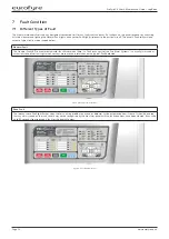
Page 12: ...e General Fault LED is a common indicator that flashes when there is a Fault on any part of the Fire Alarm Systems It is usually lit in tandem with at least one other fault light which conveys more precise information on the type of Fault detected Figure 3 General fault indication Zone Fault The relevant zone Fault light flashes when there is a wiring problem on a zone or detector has been removed...

Page 13: ...he panel will only operate for the standby period dictated by the size of the batteries fitted If the batteries or charger fails at the same time as the mains the panel will be inoperative Figure 6 Power supply fault indications System Fault The System Fault LED and General fault lights when the panel s micro processor has Reset typically after excessive electrical interference or if the contents ...

Page 14: ... Fault Condition Occurs If a fault occurs the responsible person should 7 Enter the access code and press to enable controls and press to silence the fault buzzer 8 Write down the fault s in the Log Book at the back of this manual Take appropriate action to correct the fault usually by contacting the service engineer On the ProFyre C8 panel the fault indications except system fault are non latchin...

Page 15: ...annot be disabled External sounders can also be disabled as could be required in certain conditions 8 2 To Disable Enable a Zone and or External Sounders 1 Enter the access code default 1245 and press 2 Hold the for 3 seconds 3 Type the number of the zone you want to disable If you want to disable a sounder press 4 Press to disable the selected zone or sounder 5 To exit the disable mode Hold down ...

Page 16: ...t 1245 Press Press again to deactivate sounder delay 9 3 How the Panel Indicates Sounder Delay If a Delay has been programmed into the panel the General Disablement Delay LEDs will be lit When a zone processes an alarm signal the panel will indicate fire in the usual way but the sounders will not be active until the delay period has expired To override this delay press delay Override Switch which ...

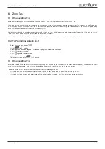
Page 17: ...mode if the user needs to access another function e g disable 10 2 To Programme Zone in Test 1 Enter access code and press 2 Hold for 3 seconds 3 Select the zone you want to go in test mode by typing the number with the keypad 4 Press to start test mode 5 Press again to stop test mode 6 To leave test mode hold for 3 seconds 10 1 Why use Zone Test Test mode provides a way to test a system without i...

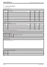
Page 18: ...A brief description of all the rooms and areas contained in each zone Sounder Qty Bell Qty Strobe Qty 1 2 3 4 Any other information about the sounder circuits Output Routing Information Type of Output Connected What happens when activated Auxiliary Output Yes No Fault Output Yes No Additional Information Any additional information the user needs to know about should be inserted into this box inclu...

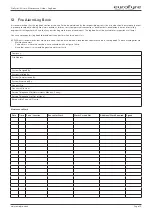
Page 19: ...ou can photocopy this log book to provide extra pages for when this book is full BS 5839 part 1 recommends that fire alarm events should be subdivided recorded on separate sheets in the log book The event categories are Maintenance work False alarms where the sounders have activated with no signs of a fire Any other events this would be genuine alarms or faults Company Site Address System Designed...

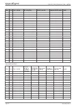
Page 20: ...e Zone Location Reason for Work Works Carried Out Additional Work Required Signed Unwanted False Alarms Date Time Zone Location Cause if Known or Activities in Alarm Area Maintenance Visit Needed Yes No Maintenance Findings Category of False Alarms Further Action Required Signed ...

Page 21: ...n or Activities in Alarm Area Maintenance Visit Needed Yes No Maintenance Findings Category of False Alarms Further Action Required Signed All other events other than maintenance works or unwanted alarms Date Time Zone Location Details of Event Including Cause if Known Action Required Date Completed Initials ...

Page 22: ...ProFyre C8 User Maintenance Guide Log Book Page 22 www eurofyre co uk Date Time Zone Location Details of Event Including Cause if Known Action Required Date Completed Initials ...

Page 23: ...ignal an alarm condition and indicate the correct zone and text message on the fire alarm panel The sound pressure level throughout the building should be checked for compliance with the recommendations of BS 5839 Pt 1 2017 clause 16 2 Any deviations from BS 5839 Pt 1 clause 7 2 should be listed in the Certificate of Installation Commissioning The certificate of Installation Commissioning should b...

Page 24: ...f the signatory is limited to the system described below System Category see BS 5839 1 2017 Clause 5 Variations from the recommendations of section 2 of BS 5839 1 2017 see Clause 7 Extent of system covered by this certificate Brief description of areas protected not applicable for Category M L1 or P1 systems Measures incorporated to limit false alarms Account has to be taken of the guidance contai...

Page 25: ...n accordance with the recommendations of clause 35 2 6 of BS 5839 1 2017 it is recommended that following commissioning a soak period of should follow enter a period of at least 1 week As the system incorporates no more than 50 automatic fire detectors no soak test is necessary to satisfy the recommendations of BS 5839 1 2017 Verification Verification that the system complies with BS 5839 1 2017 s...

Page 26: ... recommendations of BS 5839 1 2017 except for the variations if any stated in this certificate Name Position Signature Date For and behalf of Address The extent of liability of the signatory is limited to the system described below Extent of the installation work covered by this certificate Specification against which the system was installed Variations from the specification and or section 4 of B...

Page 27: ...ibed below Extent of the installation work covered by this certificate Variations from the specification and or section 4 of BS 5839 1 2017 see clause 7 All equipment operates correctly Installation work is as far as can be reasonably ascertained of an acceptable standard The entire system has been inspected and tested in accordance with the recommendations of 39 2 c of BS 5839 1 2017 The system p...

Page 28: ...service visit Before the system becomes operational it should be soak tested in accordance with the recommendations of Clause 35 2 6 of BS 5839 1 2017 for a period of enter a period of 1 week the period required by the design specification or the period recommended by the signatory to this certificate whichever period is the greatest or delete if not applicable ...

Page 29: ...tem is capable of giving a fire alarm signal The facility for remote transmission of alarms to an alarm receiving centre operates correctly delete if not applicable The following documents have been provided to the purchaser or user As fitted drawings Operating and maintenance instructions Certificates of Design Installation and Commissioning A log book Sufficient representatives of the user have ...

Page 30: ...Back Page ...
Reviews: