background image

© 

EUROHEAT 

DISTRIBUTORS (H.B.S) LTD. March 2012

E & OE      Instructions Part number IN1156 Ed. E

19

Gas Connection

Harmony 45 (H45)

Connect  a  15mm  gas  supply  pipe  to  the  3/8”  connection  at  the  rear  of  the  appliance.  We  advise  that  a 
minimum supply pipe size of 15mm is utilized, (8-10mm supply pipe is not suitable).

Harmony 35 (H35) 

Bring a 15mm gas supply pipe as close as possible to the appliance connection, use an 8mm pipe for the final 
connection. Do not use more than 500mm of 8mm final connecting pipe.

Connect a suitable gas pressure gauge to the test nipple on the gas valve, see page 18, turn the gas supply on 
and check that the gas connections are sound.  If satisfactory light the appliance. Check all the gas connections 
on the appliance for leaks. The appliance is factory tested, but it is possible for a connection to have been 
disturbed during transportation and installation.

Set the control to the high setting, and check that the gas pressure is as stated on the data table.

Turn off the gas, remove the pressure gauge and refit the test point screw, turn the gas supply on and check 
that the test nipple is gas sound.

Lighting 

For full operating instructions see operation manual.

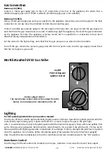
Turn the on/off knob, smaller right hand knob, slightly counter-clockwise towards the ignition position until the 
control knob stops turning, press it down and hold for 5 seconds to allow the gas to the pilot light.
After  5 seconds turn the control to the pilot position with the knob still depressed. There will be an audible click 
as the Piezo spark is generated. Hold down the control knob for 30 seconds if the pilot has lit, if it has not lit 
then repeat the pilot lighting procedure to maximum of 6 attempts. If after 6 attempts the pilot has not ignited 
leave the appliance for 5 minutes before attempting again. (This assumes the system has been purged) 
Once the pilot has been established, let out the control knob and turn it anticlockwise to the “ON” position.

Main Burner Control

Turn the larger left hand control anti clockwise to increase, clockwise to decrease the desired heat output. 

Burner output control.

The main burner control will set the output from the 

burner, from maximum to minimum and to off. 

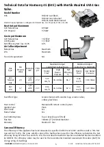
Mertik Maxitrol GV34 Gas Valve

On/Off

Pilot Setting and 

Ignition Control

Summary of Contents for Harmony 35

Page 1: ...PART NUMBER SERIAL NUMBER Installation Servicing Instructions Harmony 35 Harmony 45 Balanced Flue Gas Stoves IN1156 Edition E March 2012 ...

Page 2: ...ir Collar Adjustment 25 Servicing Instructions 26 Burner Removal and Replacement 27 Thermocouple Replacement 29 Door Handle Adjustment 31 Lower Door Opening and Level Adjustment 31 Balanced Flue Stove Technical Guide Document No IN1105 When installing the stove this document should be used in conjunction with the Euroheat Balanced Flue Technical Guide Document No IN1105 Information from the Eurohe...

Page 3: ...nstallation of Gas Fires BS 5482 PT 1 1994 LPG Installations BS 6891 1998 Pipe Work Installation d It is important to ensure that the flue system on which the appliance is to be installed is fitted in accordance to Euroheat s Balanced Flue Technical Guide Document No IN1105 It is therefore important in the interests of safety that these instructions are strictly followed together with the legal St...

Page 4: ...rranty Standard 1 Year Seasonal Efficiency The efficiency of this appliance has been measured as specified in BS EN 613 2001 and the result is 77 9 Nat Gas and 80 2 LPG The gross calorific value of the fuel has been used for this efficiency calculation the Net efficiency being 86 Nat Gas and 86 LPG The test data from which it has been calculated has been certified by BELTEST The efficiency value m...

Page 5: ...ameter Warranty Standard 1 Year Seasonal Efficiency The efficiency of this appliance has been measured as specified in BS EN 613 2001 and the result is 78 Nat Gas and 80 7 LPG The gross calorific value of the fuel has been used for this efficiency calculation the Net efficiency being 87 Nat Gas and 87 LPG The test data from which it has been calculated has been certified by BELTEST The efficiency ...

Page 6: ...o installation to allow for levelling the stove on an uneven hearth The plastic hearth protectors can be put under the feet to protect the hearth when sliding the stove into position but should be removed unless required to help level the stove Enamel Repair Touch Up Enamel Stoves Only In the plastic bag within the stove there will be a bottle or tube of enamel touch up which will match the enamel...

Page 7: ... complete the form on pages 3 and 4 and return it with a copy of your sales receipt from your Euroheat approved supplier to obtain your THREE GOOD REASONS Why you should have your stove commissioned It is vital for the longevity and efficient and safe operation of the stove to have the stove installed and commissioned by a competent qualified heating engineer 1 Installation The stove should be ins...

Page 8: ...sure for many years Minimum clearance from combustible materials Minimum clearance from non combustible materials A 12 300mm 9 230mm B 6 150mm 4 100mm C 1 25mm N A D 2 50mm 2 50mm E 6 150mm 4 100mm F 12mm of non combustable material 12mm of non combustable material Curtains and furnishings should be a minimum of 1m from the stove The stove can be placed on a combustible floor providing it can supp...

Page 9: ...e of delivering the required amount of gas and is in accordance with the relevant current standards It is generally preferred to conceal the gas supply by bringing it under the hearth or through masonry to the side of the fireplace Any pipe work in 8mm tube connecting the stove to the main pipe work should be kept as short as possible with as few fittings as possible to prevent restrictions a When...

Page 10: ...elow Ensure that the choke plate fitted is correct for the gas type and flue configuration to be installed this information is in the Balanced Flue Stove Technical Guide IN1105 If not replace with the correct choke plate which can be found in the bag of installation accessories Inside the stove in the bag of installation accessories will be the flue spigot gasket and two M5 screws to fit the cast ...

Page 11: ...ner steel blanking plate on the rear of the stove Twist the blanking plate so that the plate lifts over the screws 4 Align the inner flue adapter pipe with the screws and twist it so it locks into position Tighten the four screws to ensure a good seal NOTE Do not fit the choke plate to the rear outlet as it will restrict the air flow and stall the flue gasses and the stove will not work ...

Page 12: ...ve 6 Fit the rear inner blanking plate to the top of the stove see picture below The stove will not run if this part is omitted 7 Fit the gasket and rear blanking plate onto the top flue exit using the countersunkscrews If it has an enamel finish the cup washers should also be used to protect the enamel finish Cup washer for enamelled finished stoves ...

Page 13: ...e flue pipes together and to the flue spigot collar on the stove Some of these so called Heat Proof mastiks will only stand a temperature of 300 C before they start breaking down In many cases they may give off an obnoxious smell at temperatures much lower than this Please ensure that the jointing compound used is suitable if in doubt contact the manufacturer of the sealing compound before you use...

Page 14: ...ty for accidental damage so great care should be taken when handling the ceramic burner and logs It is important that the logs ember glow fibres and ember cubes are installed in accordance with these instructions as any deviation may cause poor combustion The addition of further ceramic logs or cubes is strictly prohibited Back log Left log Front log Ceramic burner Burner and Log Set Components Em...

Page 15: ...eezers when placing the embers in position Wash hands immediately after touching to avoid irritation Do not store the embers close to flammable liquids The embers must be placed correctly in order to function properly Tease out the fabric to form loose irregular shapes Use of Embers With the embers correctly placed they glow and flicker similar to glowing ash Their placement is important as the ef...

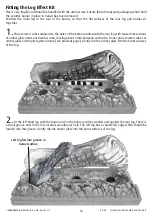
Page 16: ...holes of the burner underneath the rear log with teased out sections of ember glow under each ember cube leaving about 5mm between each cube Do not place ceramic cubes or ember glow on the pilot ignition route see previous page Gently rub the ember glow into the burnt surfaces of the log 2 Fit the left hand log with the larger end on the burner and the smaller end against the rear log There is a s...

Page 17: ...re of the burner is a groove for the front log to be located Gently rub ember glow into the burnt surfaces of the log Place ceramic ember cubes along the holes of the burner in front of and to the sides of the right hand log with teased out sections of ember glow under each ember cube leaving about 5mm between each cube ...

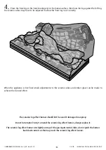
Page 18: ...to sit correctly The ceramic log effect burner should NOT be used if damaged in anyway Do not be tempted to try to mend the ceramic log effect burner always replace it The ceramic log effect burner sits lightly on top of the gas input venturi tube do not push the burner hard down onto it as this may crack the ceramic log effect burner When the appliance is first fired small adjustments to the cera...

Page 19: ...e test point screw turn the gas supply on and check that the test nipple is gas sound Lighting For full operating instructions see operation manual Turn the on off knob smaller right hand knob slightly counter clockwise towards the ignition position until the control knob stops turning press it down and hold for 5 seconds to allow the gas to the pilot light After 5 seconds turn the control to the ...

Page 20: ...screws are located under the cover To remove the cover first loosen the screw next to the temperature knob Insert the tip of a small screwdriver into the slot on the top of the front cover next to the on off knob push downwards and lift the cover off _ Pilot flame adjustment screw preset at factory Operating pressure adjustment screw The direction is indicated on the brass cover of the adjustment ...

Page 21: ...e Test Nipple Locations Note the test nipple sealing screw cannot be removed System Pressure Test Nipple Line Pressure Operating Pressure Test Nipple Access to the test nipples can be obtained from below the valve see picture below Micro switch on models where the remote control option has been fitted ...

Page 22: ...ger connectors fit to the motor Note these two connectors are different in size and fit only to the appropriate sized connector on the motor Receiver location Place the receiver on the stove hearth under the gas valve NOTE Ensure that the receiver will accept instructions from the handset They must match each others coding and the instructions for this are in the operating instructions Operating I...

Page 23: ... operating pressure Adjust if required e Carry out a low burn operating pressure test Attach a manometer to the operating pressure test nipple see page 20 Turn the gas valve control knob to the minimum flame size Observe the operating pressure Adjust if required f Carry out a gas supply pressure test with the appliance operating Attach a manometer to the supply pressure test nipple see page 20 Ope...

Page 24: ...eration if the remote thermostatic option has been fitted e The stove imitates a solid fuel stove and like a solid fuel stove ITS SURFACES BECOME VERY HOT f Do not use the appliance if the glass is cracked or broken h Do not use the appliance if any of the ceramic log effect components are broken i The appliance must be guarded to protect children the aged or infirm j Do not operate the appliance ...

Page 25: ... adjust the operating pressure adjustment screw for the gas type to be used See pages 4 5 for gas valve technical data for required pressure e The low fire operating pressure will require adjustment Light the stove and turn the control knob to a position which gives a low fire operation of the flame i e the stove operates in three modes 1 Pilot position 2 Low fire 3 High fire full output Check the...

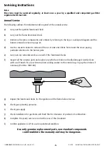
Page 26: ...from inside the stove paying particular attention to the burner ports e Carry out any remedial work as a result of the functional checks f Inspect all the ceramic parts and replace any which are broken or badly damaged Gently clean with a soft brush Fit a new 10mm silicon sealing washer to the venturi cup Top up the embers if necessary Part No MS9180 g Repeat the functional checks for the ignition...

Page 27: ...ft the burner back into the stove The two adjustable side brackets should then be replaced these brackets should be adjusted so that the burner is level and when the centre is pushed down there is 1 to 2mm movement see page 27 H45 Burner Removal and Replacement Removal Remove the logs from the top of the burner Theburnerisheldinplacebytwoadjustable brackets which secure the burner and allow it to ...

Page 28: ...urner should be pushed downwards at a position above the supporting cup to confirm that the burner is able to compress the sealing washer a further one or two millimetres The burner should be level and stable 10mm Silicon sealing washer Push down on centre of burner to check the burner is sitting properly on the silicon sealing washer Replace the log effect Follow the instructions on pages 12 to 1...

Page 29: ...e gas supply at the isolation valve and then remove the gas connection to the stove 2 Remove the log or coal effect kit from on top of the burner matrix Take care as the ceramics are very fragile and are not covered under the stoves warranty where damage has been sustained through rough handling 3 Remove the burner matrix from within the stove There may be brackets holding the base matrix in place...

Page 30: ...Remove the 6 bolts holding the burner tray to the bottom of the stove lower the burner tray down and withdraw the whole tray from the body of the stove 7 Using a 10mm spanner loosen the thermocouple retaining nut underneath the pilot assembly and withdraw the thermocouple sensor Remove and retain the securing nut from the thermocouple as this will be required to fit the new thermocouple 8 Remove t...

Page 31: ...ten the nut holding the thermocouple in position 6 Replace the burner base log or coal effect and embers Ensure that the burner base is sitting correctly on the burner seal below see pages 26 27 7 Check the operation of the main burner ensuring that the burner lights within 3 seconds Door Handle Adjustment It is very important for the correct operation of the stove that the furnace door glass door...

Page 32: ...5 491112 Technical 01885 491117 Reception 01885 491100 Need more info with over 10 000 pages of technical information spare parts product shots news and 1001 other things you will not find a more comprehensive solution to your queries whatever time of the day www euroheat co uk ...

Reviews: