background image

Installations

 (refer to Page 4 for parts)

:

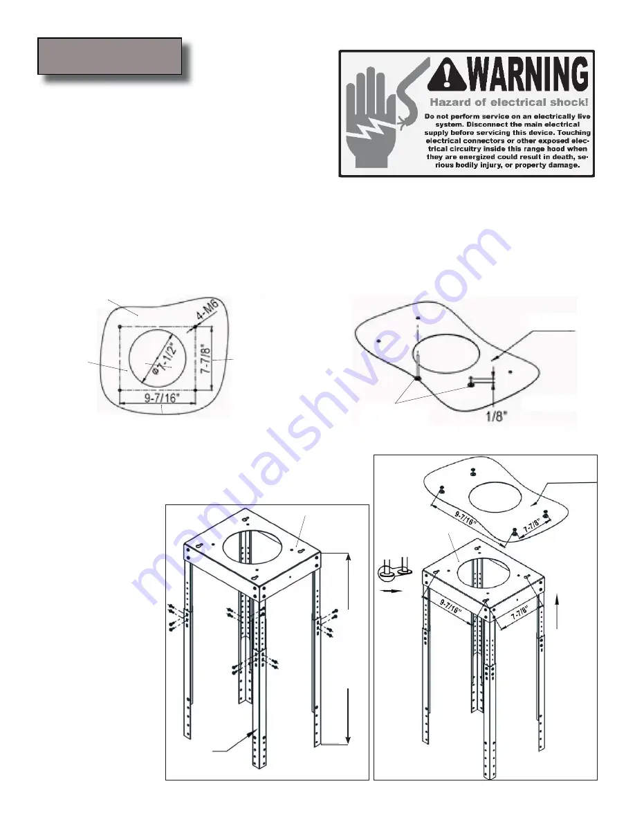
As illustrated in Figure 1A, drill four holes with diam-

1.

eter not exceeding 5/8” and depth of 3” to 3-1/2” on the 
false ceiling. Fasten two hexagonal wood screws  at two 
of these holes opposite from each other, reserve approx-
imately 1/8” for the top support plate as shown in Fiture 
1B. Cut out a circle of 7-1/2” diameter for duct work. Use appropriate anchors for your ceiling composition:

Wood ceiling: Use the provided hexagonal wood screw.

• 

Sheet rock ceiling: Attach top supporting plate to ceiling joists or stud blockings if possible. If ceiling 

• 

joists or stud blockings are not available, it is required to build a supporting structure behind the sheet 
rock for best weight support.

Concrete ceiling: Use designated screws (not provided).

• 

Place support frames inside the top support plate, adjust 

2.

support frames to lengh required and lock the support 
frames using sixteen (16) 4mm x 8mm Phillips Head Tap-
ping Screw as shown in Figure 2.

Support 
Frames

Length required

Figure 2

Align the holes in top 

3.

support plate with two 
screws on the ceiling. 
Push upward (1) and 
slide forward (2) so 
the top supporting 
plate locks into place, 
see Figure 3. Fasten 
two existing hex-
agonal wood screws, 
insert two more on 
the last two holes 
and fasten them.. 

CAUTION: MAKE 
SURE the support 
frame fixture is secure 
before releasing!

Figure 3

Ceiling

(2) Slide 
Forward

(1) Push 
Upward

Front of the hood

Ceiling

Side of 
the hood

Ceiling

Top 

Support 

Plate

Figure 1A

Figure 1B

Hexagonal 
Wood Screws

Top Support 
Plate

Top Support 

Plate

Installation

Page 10

Summary of Contents for Spagna Vetro SV218E-IM

Page 1: ...sers Manual Island Mount Range Hood SPAGNA VETRO 218 Series SV218E IM NOTICE Installer Leave this guide with the homeowner Homeowner Keep this guide for future reference IMPORTANT Read and save these instructions Rev 2025u 1b ...

Page 2: ......

Page 3: ...de authorities Before servicing or cleaning unit switch power OFF at service panel and lock service panel to pre vent power from being switched ON accidentally Clean grease laden surfaces frequently To reduce the risk of fire and to disperse air properly make sure to vent air outside DO NOT vent exhaust into spaces between walls crawl spaces ceiling attics or garages Ducted fans MUST always be vent...

Page 4: ... go out immediately EVACUATE AND CALL THE FIRE DEPARTMENT or dial your local emergency service immediately DO NOT USE WATER including wet dishcloths or towels a violent steam explosion will result Use an extinguisher ONLY if You know you have a Class A B C extinguisher and you already know how to operate it The fire is small and contained in the area where it is started The fire department is being ...

Page 5: ...t heights clearance 5 6 Calculating vent system length 6 Venting methods 7 Ductless conversion 7 Charcoal filters electrical requirements 8 Preparation 9 Installation 10 12 USE AND CARE Range hood operations 13 14 Troubleshooting 15 Use and care information 16 Specifications 16 Wiring diagram 17 MAINTENANCE Cleaning replacing filter light bulb 18 WARRANTY Coverage exceptions 19 Disclaimer contact inf...

Page 6: ...nd Warranty Card 1 Set 4mm x 16mm Round Phillips Head Screw 18 Pcs 4mm x 16mm Phillips Head Tapping Screw 24 Pcs 4mm x 8mm Phillips Head Tapping Screw 16 Pcs Optional 4mm x 8mm Phillips Head Tapping Screw for Air Diverter 4 Pcs Optional Phillips Head Screw for Charcoal Filter 2 Pcs Charcoal Filter Optional re circulating kit Support Frame Structure Flappers Ra Parts supplied Lower standard chimney...

Page 7: ...oun 2 tertop stove recommend 28 to 31 Distance between the countertop stove 3 to the range hood Height of hood and duct cover 4 For the most efficient quiet operation A distance of 28 to 31 is recommended between stove top and the bottom of range hood It is recommended that the range hood be vented vertically through the roof through 6 15 24 cm or bigger round metal aluminum vent work The size of t...

Page 8: ...sing elbows transitions and caps ALWAYS when possible reduce the number or transitions and turns If long duct run is required increase duct size from 6 to 7 or 8 If a reducer is used install a long reducer instead of a pancake reducer Reduc ing duct size will restrict airflow and decrease airflow thus reduce duct size as far away from opening as pos sible If turns or transitions are required Install...

Page 9: ...tless conversion is intended for applications where an exhaust duct work is not possible to be installed When converted the hood functions as a purifying hood rather than an exhaust hood Fumes and exhaust from cooking is drawn and filtered by a set of charcoal filters The air is then purified and re circulated back within the home We recommend to ALWAYS exhaust air outside of the home by employing ex...

Page 10: ...circuit breaker box through flexible armored or non metallic sheathed copper cable A U L or C S A listed strain relief must be provided at each end of the power supply cable Wire sizes copper wire only and connections must conform with the rating of the appliance as specified on the model serial rating label Wire sizes must conform to the requirements of the National Electrical Code ANSI NFPA 70 lat...

Page 11: ...support mounting bracket holes vent cutout if used and power supply cable cutout 4 on the ceiling Use drill and saber saw or keyhole saw to cut openings for power supply cable and vent see Venting requirements and Electrical requirements Pages 5 8 If venting to the outside install vent system see 5 Venting Methods Page 7 Use caulking to seal exterior wall or roof openings Disconnect main electrica...

Page 12: ...hind the sheet rock for best weight support Concrete ceiling Use designated screws not provided Place support frames inside the top support plate adjust 2 support frames to lengh required and lock the support frames using sixteen 16 4mm x 8mm Phillips Head Tap ping Screw as shown in Figure 2 Support Frames Length required Figure 2 Align the holes in top 3 supportplatewithtwo screws on the ceiling ...

Page 13: ...re all joints are secured and air tight Figure 5 Figure 4A Figure 4C Figure 4B Slide both chimneys upward Recirculating Non Vented Kit If Re Circulating Kit is not purchased skip this step Place the air diverter inside support frame so that its 6 round hole faces downward and secure it with four 4mm x 8mm Phillips Head Tapping Screws Air Diverter Optional Support Frames Ceiling Upper Chimney has v...

Page 14: ... slide down both chimneys until they sit on the hood Connect the duct work and connect the power cable see figure 7A Bring only the upper chimney up until it reaches the ceiling secure it with two 4mm x 16mm Round Phillips Head Screws as shown in Figure 7B 4mm x 16mm Round Phillips Head Screws Recirculating Non Vented Kit If Re Circulating Kit is not purchased skip this step Install the duct tube o...

Page 15: ...e accumulated time the system is running Power Off Delay Digital Timer Indicates the length of time left for delay off function Power Off Delay Timer Indicator Lights up when auto shutdown delay timer function is on Controls Automatic cleaning reminder This range hood is equipped with a cleaning reminder that will activate following 30 hours of use When blower motor starts to rotate cumulative run...

Page 16: ... will shut down Adjusting the light Press Light button once to turn on the lights and once again to turn off the lights While the lights are off press and hold Light button for over 3 seconds to dim the lights from low to high Level of brightness will be stored in system s memory CAUTION DO NOT touch the lights until switched OFFand cooled Note Light settings are independent from other settings in...

Page 17: ...t installed correctly or opening properly A tight mesh on a side wall cap unit might also cause restriction to the air flow The lights work but the blower is not spinning at all 4 is stuck or is rattling The blower might be jammed or scraping the bot tom due to shipping damage Please contact us im mediately The hood is not venting out properly 5 Make sure the distance between the stove top and the ...

Page 18: ...Always leave safety grills and filters in place Without these components operating blowers could catch on to hair fingers and loose clothing NEVER dispose cigarette ashes ignitable substances or any foreign objects into blowers NEVER leave cooking unattended When frying oil in the pan can easily overheat and catch fire The risk of self combustion is higher when the oil has been used several times NEV...

Page 19: ...Page 17 Wiring Diagram Six Speed with Type GU10 Bulb Six Speed with Type MR16 Bulb ...

Page 20: ...l wool or steel brushes Small bits of steel may adhere to the surface and cause rusting DO NOT allow salt solutions disinfectants bleaches or cleaning compounds to remain in contact with stainless steel for extended periods Many of these compounds contain chemicals which may be harmful Rinse with water after ex posure and wipe dry with a clean cloth Cleaning Aluminum Grease Filter Stainless Steel ...

Page 21: ...tallation Damage of product caused by accident fire floods or act of God The manufacturer and or distributor reseller is not liable for and does not cover under warranty any loss of properties or any costs associated with removing servicing installing or determining the source of problems with this product This warranty is valid in the country of the original purchase at retail It is non transferabl...

Page 22: ...g fee of 15 will be charged for all approved return s Exchanges or returns may not be accepted if any packaging is missing Make sure to inspect the hood for damages and defects before installation Appearance flaws of the hood found after installation and not affecting hood performance is not covered under our warranty for returns or exchang es Service visits not covered under warranty will carry a ...

Page 23: ...Your Notes Page 21 ...

Page 24: ...Euro Kitchen Inc 2341 Industrial Parkway West Hayward CA 94545 Ph 510 266 0099 Fax 510 266 6630 http www euro kitchen com ...

Reviews: