00085144.DOCX, Version 1.0
13/16
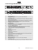
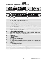
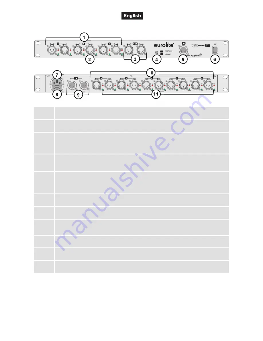
4. OPERATING ELEMENTS AND CONNECTIONS
1
DMX512 outputs 1 - 3
Rear DMX outputs 1 to 3 to connect further DMX chains.
2
Status indi and ‒
DC (red) = port is powered, SIGN (green) = DMX signal is present.
3
DMX512 feed-through output
Direct DMX output for connecting additional DMX devices or DMX splitters within the same
DMX chain as the DMX input. This output is only active when the TERMINATE/LINK OUT
selector switch is not pressed.
4
QuickDMX input
DMX signal input (5-pin XLR) for connecting a wireless QuickDMX receiver. The connector
provides the required 5 V operating voltage.
5
TERMINATE/LINK OUT selector switch
• Switch pressed: The DMX line of the DMX input is terminated by a resistor. The feed-through
DMX output is disabled.
•
Switch not pressed: The feed-through DMX output is active.
6
Power switch
Turns the unit on and off.
7
Power
input
Used to plug the supplied power cord in.
8
Fuse holder
Only replace the fuse when the device is disconnected from mains. Only use fuses of the same
rating and power. The correct value is specified on the device.
9
DMX512 input
For connecting the DMX control signal.
10
DMX512 outputs 4 - 8
Rear DMX outputs 4 to 8 to connect further DMX chains.
11
Status indi and ‒
DC (red) = port is powered, SIGN (green) = DMX signal is present.
4
5
6
2
3
8
7
9
11
1
10


