00085144.DOCX, Version 1.0
14/16
5. INSTALLATION AND CONNECTIONS
Installation
Install the unit on a plane surface or in a rack. The rack should be provided with doors on the front and rear
panel and a cooling fan. When mounting the device into the rack, please make sure that there is enough
space around the device so that the heated air can be passed on. Steady overheating will damage your
device. You can fix the device with four screws M6 in the rack
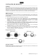
DMX512 Connection
Switch off the DMX splitter prior to connecting any units or to changing any existing connections. For
connection, use special DMX cables for high data flow.
1
Feed the DMX control signal to the rear XLR input IN.
2
The unit features an alternative DMX input for a QuickDMX receiver (sold separately). This connector
allows for wireless transmission of DMX control signals to the splitter. The connector is designed as a
5-pin XLR mounting plug which provides the required 5 V operating voltage for the receiver.
3
Each of the unit's DMX outputs 1 to 8 allows connection of one DMX chain, which in turn may consist of
a maximum of 32 DMX devices. At the last fixture in the DMX chain, the DMX line has to be terminated
by a resistor (120 Ω).
4
If the DMX Split 8X should terminate a DMX chain, press the TERMINATE/LINK OUT selector switch.
Then a termination resistor is connected.
5
You can connect an additional DMX Split 8X or DMX chain with up to 32 DMX devices to the DMX feed-
through output OUT. In order to use this output, release the TERMINATE/LINK OUT selector switch.
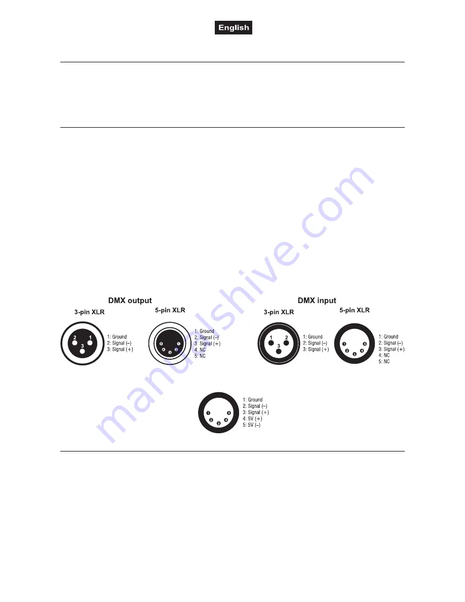
Occupation of the XLR connection:
Occupation of the QuickDMX connection:
Connection with the Mains
Connect the device to the mains with the power plug. The device uses an auto-range power supply that
accepts input voltages between 100 und 240 volts.

