
00085144.DOCX, Version 1.0
15/16
6. CLEANING AND MAINTENANCE
We recommend a frequent cleaning of the device. Please use a soft lint-free and moistened cloth. Never use
alcohol or solvents!
There are no serviceable parts inside the device except for the fuses. Maintenance and service operations
are only to be carried out by authorized dealers.
Replacing the Fuse
If one of the fine-wire fuses of the device fuses, only replace the fuse by a fuse of same type and rating.
Before replacing the fuse, unplug mains lead.
Procedure:
Step 1:
Open the fuseholder on the rear panel with a fitting screwdriver.
Step 2:
Remove the old fuse from the fuseholder.
Step 3:
Install the new fuse in the fuseholder.
Step 4:
Replace the fuseholder in the housing.
Should you need any spare parts, please use genuine parts.
If the power supply cable of this device becomes damaged, it has to be replaced by a special power supply
cable available at your dealer.
Should you have further questions, please contact your dealer.
7. TECHNICAL SPECIFICATIONS
Power supply:
100-240 V AC, 50/60 Hz ~
Power consumption:
5 W
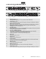
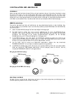
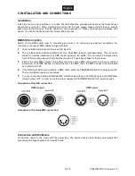
DMX512 connection:
3-pin and 5-pin XLR
QuickDMX connection:
5-pin XLR
Dimensions (LxWxH):
483 x 145 x 45 mm
Weight:
2 kg
Accessory
Item 70064702
QuickDMX Wireless receiver phantom-power
Please note: All information is subject to change without prior notice. 07.08.2014 ©
Disconnect from mains before starting maintenance operation!
DANGER TO LIFE!


