background image

00050719.DOC, Version 1.2

18/22

The durability of the installation depends very much on the material used at the installation area (building
material) such as wood, concrete, gas concrete, brick etc. This is why the fixing material must be chosen to
suit the wall material. Always ask a specialist for the correct plug/screw combination indicating the maximum
load and the building material.

Procedure:

Step 1:

 The holes for the installation are on the mounting brackets.

Step 2:

 Hold the mounting brackets onto the location where the device is to be installed.

Step 3:

 Mark the boreholes with a pen or a suitable tool.

Step 4:

 Drill the holes.

Step 5:

 Hold the mounting brackets in the desired position and tighten it.

DANGER TO LIFE!

Before taking into operation for the first time, the installation has to be approved by an expert!

DMX-512 control

The wires must not come into contact with each other, otherwise

the devices will not work at all, or will not work properly.

Please note, the starting address depends upon which controller is being used.

Only use a DMX-cable and 3-pin XLR-plugs and connectors in order to connect the controller with the fixture
or one fixture with another.

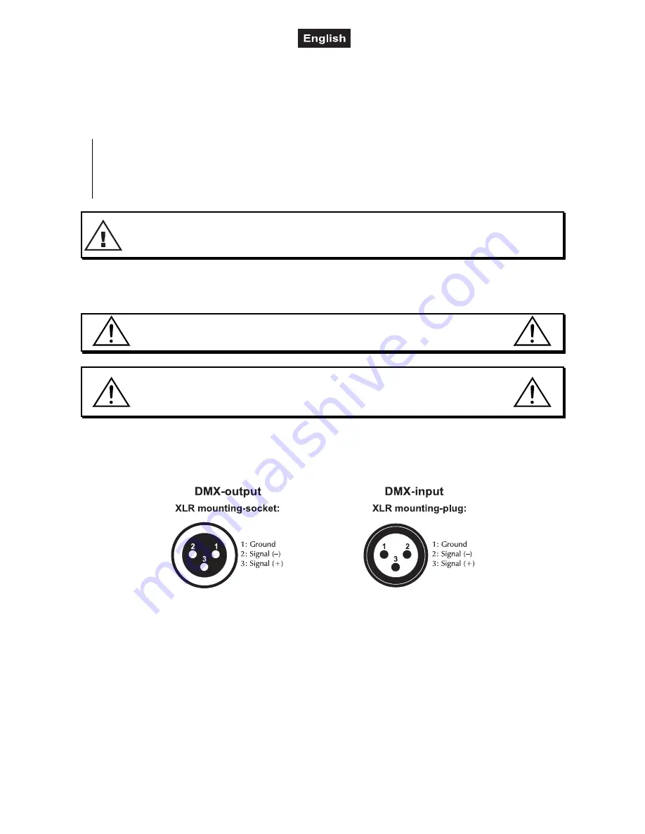
Occupation of the XLR connection:

If you are using controllers with this occupation, you can connect the DMX output of the controller directly
with the DMX input of the first device in the DMX chain. If you wish to connect DMX controllers with other
XLR outputs, you need to use adapter cables.

Building a serial DMX chain:

Connect the DMX output of the first device in the DMX chain with the DMX input of the next device. Always
connect one output with the input of the next device until all devices are connected.

Caution: 

At the last fixture, the DMX-cable has to be terminated. Plug the terminator with a 120 

resistor

between Signal (–) and Signal (+) in the DMX-output of the last fixture.

Summary of Contents for LED Bar RGB 126/10 20

Page 1: ... Copyright Nachdruck verboten Reproduction prohibited Für weiteren Gebrauch aufbewahren Keep this manual for future needs BEDIENUNGSANLEITUNG USER MANUAL LED Bar RGB 126 10 20 LED Bar RGB 126 10 40 ...

Page 2: ...NTRODUCTION 13 SAFETY INSTRUCTIONS 13 OPERATING DETERMINATIONS 15 OVERVIEW 16 INSTALLATION 16 OPERATION 19 DIP SWITCH CONTROLLED OPERATION 20 DMX CONTROLLED OPERATION 21 CLEANING AND MAINTENANCE 22 TECHNICAL SPECIFICATIONS 22 Diese Bedienungsanleitung gilt für die Artikelnummern This user manual is valid for the article numbers 51930416 51930417 Das neueste Update dieser Bedienungsanleitung finden...

Page 3: ...euen uns dass Sie sich für einen EUROLITE LED Bar RGB 126 10 entschieden haben Wenn Sie nachfolgende Hinweise beachten sind wir sicher dass Sie lange Zeit Freude an Ihrem Kauf haben werden Lieferumfang 1 Gerät 1 Bedienungsanleitung Nehmen Sie den LED Bar RGB 126 10 aus der Verpackung SICHERHEITSHINWEISE ACHTUNG Seien Sie besonders vorsichtig beim Umgang mit gefährlicher Netzspannung Bei die ser Sp...

Page 4: ...gungen Werden Verlängerungsleitungen verwendet muss sichergestellt werden dass der Adernquerschnitt für die benötigte Stromzufuhr des Gerätes zugelassen ist Alle Warnhinweise für die Netzleitung gelten auch für evtl Verlängerungsleitungen Gerät bei Nichtbenutzung und vor jeder Reinigung vom Netz trennen Fassen Sie dazu den Netzstecker an der Griffläche an und ziehen Sie niemals an der Netzleitung ...

Page 5: ...egen Halten Sie das Gerät von direkter Sonneneinstrahlung auch beim Transport in geschlossenen Wägen und Heizkörpern fern Die relative Luftfeuchte darf 50 bei einer Umgebungstemperatur von 45 C nicht überschreiten Dieses Gerät darf nur in einer Höhenlage zwischen 20 und 2000 m über NN betrieben werden Verwenden Sie das Gerät nicht bei Gewitter Überspannung könnte das Gerät zerstören Das Gerät bei ...

Page 6: ...ten Fachhandel ausgeführt werden Die Aufhängevorrichtungen des Gerätes muss so gebaut und bemessen sein dass sie 1 Stunde lang ohne dauernde schädliche Deformierung das 10 fache der Nutzlast aushalten kann Die Installation muss immer mit einer zweiten unabhängigen Aufhängung z B einem geeigneten Fangnetz erfolgen Diese zweite Aufhängung muss so beschaffen und angebracht sein dass im Fehlerfall der...

Page 7: ...tte darauf dass sich im Abstand von mind 0 5 m keine leicht entflammbaren Materialien Deko etc befinden BRANDGEFAHR Befestigen Sie das Gerät über geeignete Haken an Ihrem Traversensystem Sichern Sie das Gerät bei Überkopfmontage immer mit einem geeigneten Sicherungsseil Es dürfen nur Sicherungsseile gemäß DIN 56927 Schnellverbindungsglieder gemäß DIN 56926 Schäkel gemäß DIN EN 1677 1 und BGV C1 Ke...

Page 8: ...s die Schrauben fest mit dem Untergrund verbunden sind Vorgehensweise Schritt 1 An den Montagebügeln des Gerätes befinden sich die Löcher zur Installation Schritt 2 Halten Sie das Gerät mit den Montagebügeln an die Stelle wo es installiert werden soll Schritt 3 Markieren Sie Ihre Bohrlöcher mit einem Bleistift oder einem geeigneten Werkzeug Schritt 4 Bohren Sie die Löcher Schritt 5 Halten Sie das ...

Page 9: ... steuert alle weiteren Slave Geräte die über ein DMX Kabel mit dem Master Gerät verbunden werden Stecken Sie das DMX Kabel in die OUT Buchse und verbinden Sie es mit dem IN Stecker des nächsten Gerätes Stellen Sie nun den DIP Schalter 10 auf ON um das Slave Gerät festzulegen Dip Schalter 1 9 sind auf OFF Das Master Gerät ist nun in der Lage im Stand Alone Modus die Slave Geräte zu steuern Anschlus...

Page 10: ... 1 2 10 22 STEUERUNG ÜBER DIP SCHALTER DMX GESTEUERTER BETRIEB Über Ihren DMX Controller können Sie die einzelnen Geräte individuell ansteuern Dabei hat jeder DMX Kanal eine andere Belegung mit verschiedenen Eigenschaften ...

Page 11: ...n Sie sich dass sich die Steuerkanäle nicht mit anderen Geräten überlappen damit das Gerät korrekt und unabhängig von anderen Geräten in der DMX Verbindung funktioniert Werden mehrere Geräte auf eine Adresse definiert arbeiten sie synchron Belegung der DIP Schalter Gerät 1 Kanäle 1 5 Startadresse Gerätenummer Kanäle Gerät Kanäle 2 6 10 Gerät Kanäle 3 11 15 Gerät Kanäle 16 20 4 Gerät Kanäle 5 21 25...

Page 12: ...fernen Sie die defekte Sicherung aus dem Sicherungshalter Schritt 3 Setzen Sie die neue Sicherung in den Sicherungshalter ein Schritt 4 Setzen Sie den Sicherungshalter wieder im Gehäuse ein und drehen Sie ihn fest Sollten einmal Ersatzteile benötigt werden verwenden Sie bitte nur Originalersatzteile Wenn die Anschlussleitung dieses Gerätes beschädigt wird muss sie durch den autorisierten Fachhande...

Page 13: ...TION Thank you for having chosen a EUROLITE LED Bar RGB 126 10 If you follow the instructions given in this manual we are sure that you will enjoy this device for a long period of time Delivery includes 1 Device 1 User manual Unpack your LED Bar RGB 126 10 SAFETY INSTRUCTIONS CAUTION Be careful with your operations With a dangerous voltage you can suffer a dangerous electric shock when touching th...

Page 14: ...from time to time If extension cords are used make sure that the core diameter is sufficient for the required power consumption of the device All warnings concerning the power cords are also valid for possible extension cords Always disconnect from the mains when the device is not in use or before cleaning it Only handle the power cord by the plug Never pull out the plug by tugging the power cord ...

Page 15: ...device must only be operated in an altitude between 20 and 2000 m over NN Never use the device during thunderstorms Over voltage could destroy the device Always disconnect the device during thunderstorms The symbol m determines the minimum distance from lighted objects The minimum distance between light output and the illuminated surface must be more than 0 1 meters This device is only allowed for...

Page 16: ...achment must be constructed in a way that no part of the installation can fall down if the main attachment fails When rigging derigging or servicing the device staying in the area below the installation place on bridges under high working places and other endangered areas is forbidden The operator has to make sure that safety relating and machine technical installations are approved by an expert b...

Page 17: ...ng with DIN EN 1677 1 and BGV C1 carbines The safety bonds quick links shackles and the carbines must be sufficiently dimensioned and used correctly in accordance with the latest industrial safety regulations e g BGV C1 BGI 810 3 Please note for overhead rigging in public or industrial areas a series of safety instructions have to be followed that this manual can only give in part The operator mus...

Page 18: ...2 control The wires must not come into contact with each other otherwise the devices will not work at all or will not work properly Please note the starting address depends upon which controller is being used Only use a DMX cable and 3 pin XLR plugs and connectors in order to connect the controller with the fixture or one fixture with another Occupation of the XLR connection If you are using contr...

Page 19: ...mains Connect the device to the mains with the power plug The occupation of the connection cables is as follows Cable Pin International Brown Live L Blue Neutral N Yellow Green Earth The earth has to be connected If the device will be directly connected with the local power supply network a disconnection switch with a minimum opening of 3 mm at every pole has to be included in the permanent electr...

Page 20: ...00050719 DOC Version 1 2 20 22 DIP SWITCH CONTROLLED OPERATION ...

Page 21: ... for every single device by changing the DIP switches as set out in the table below The starting address is defined as the first channel from which the device will respond to the controller Please make sure that you do not have any overlapping channels in order to control each device correctly and independently from any other fixture on the DMX data link If two three or more devices are addressed ...

Page 22: ...e old fuse from the fuseholder Step 3 Install the new fuse in the fuseholder Step 4 Replace the fuseholder in the housing and fix it Should you need any spare parts please use genuine parts If the power supply cable of this device becomes damaged it has to be replaced by authorized dealers only in order to avoid hazards Should you have further questions please contact your dealer TECHNICAL SPECIFI...

Reviews: