- 23 -
ASSEMBLY
Make sure you have access to the following tools before starting to assemble the device:
Open-ended spanners 10, 13 and 17
Adjustable monkey wrench 8 inch
Water pump pliers
Medium screwdriver
Soapy liquid for leak test
Check that all of the components are present using the assembly description.
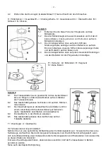
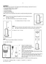
Step 1
1-1
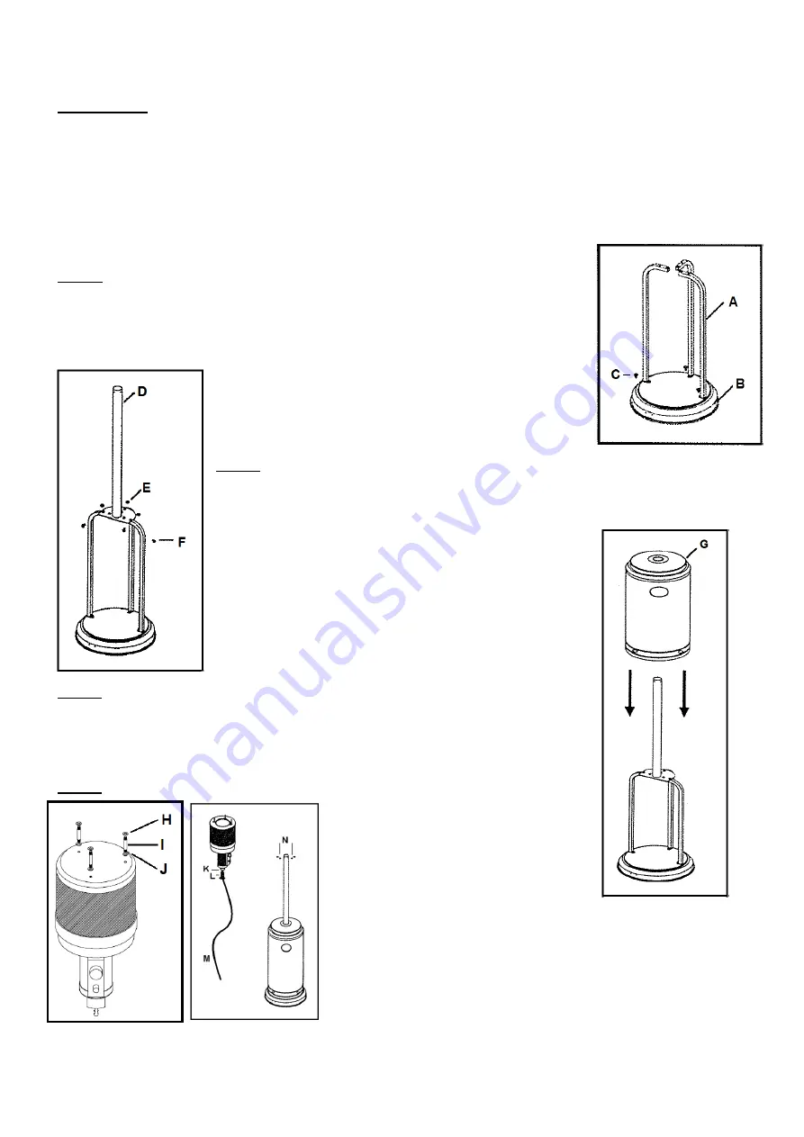
Place the three bent tubes (that together form the container frame) on
the base, see diagram.
1-2
Use 3 M8 x 16mm bolts to mount the tubes on the base.
A = container frame B = base C = bolt
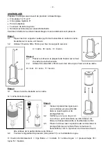
Step 2
2-3
Place the stand with the attachment plate on top of the container frame.
2-4
Use 6 M6 x 35mm bolts with nuts to mount the stand on the frame.
D = stand E = nut F = bolt
Step 3
3-1
Place the gas bottle container over the frame.
G = gas bottle container
Step 4
4-1
Screw the headless screws
(with the washer in between)
with the other side held fast into
the upper cap of the flame
screen.
4-2
Check if the rubber gas hose is
firmly mounted to the underside of the burner and allow
this to drop into the stand.
4-3
Place the burner with the operation panel and the flame
screen on the stand and secure with 4 M6 x 10mm
bolts. The 4 bolts must be removed from the bottom of
the burner firstly.
4-4
Screw pressure regulator (open-ended spanner 17) tight to the end of the gas hose.
H = stay bolt I = headless screw J = washer K = gas inlet L = swivel nut
M = hose N = bolts
Summary of Contents for THG14000
Page 38: ...38...
Page 39: ...39...
Page 40: ...40 EUROM Kokosstraat 20 8281 JC Genemuiden info euromac nl www euromac nl...


