


USER MANUAL
PG 21
CONNECTION TO THE
GAS SUPPLY
The isolating manual shut-off valve connection point must be installed and accessible when the appliance
is in position. Gas inlet is located at the top rear right hand side, 50mm from the edge. This appliance
is suitable for connection with rigid pipe or flexible hose. For flexible hose connection, the flexible hose
assembly must be certified to AS/NZS 1869 class B or D, be of appropriate internal diameter for the total gas
consumption, be kept as short as possible (not exceeding 1200mm), must not be in contact with the floor or
any hot or sharp surfaces. The hose assembly must not be subject to strain, abrasion, kinking or deformation.
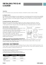
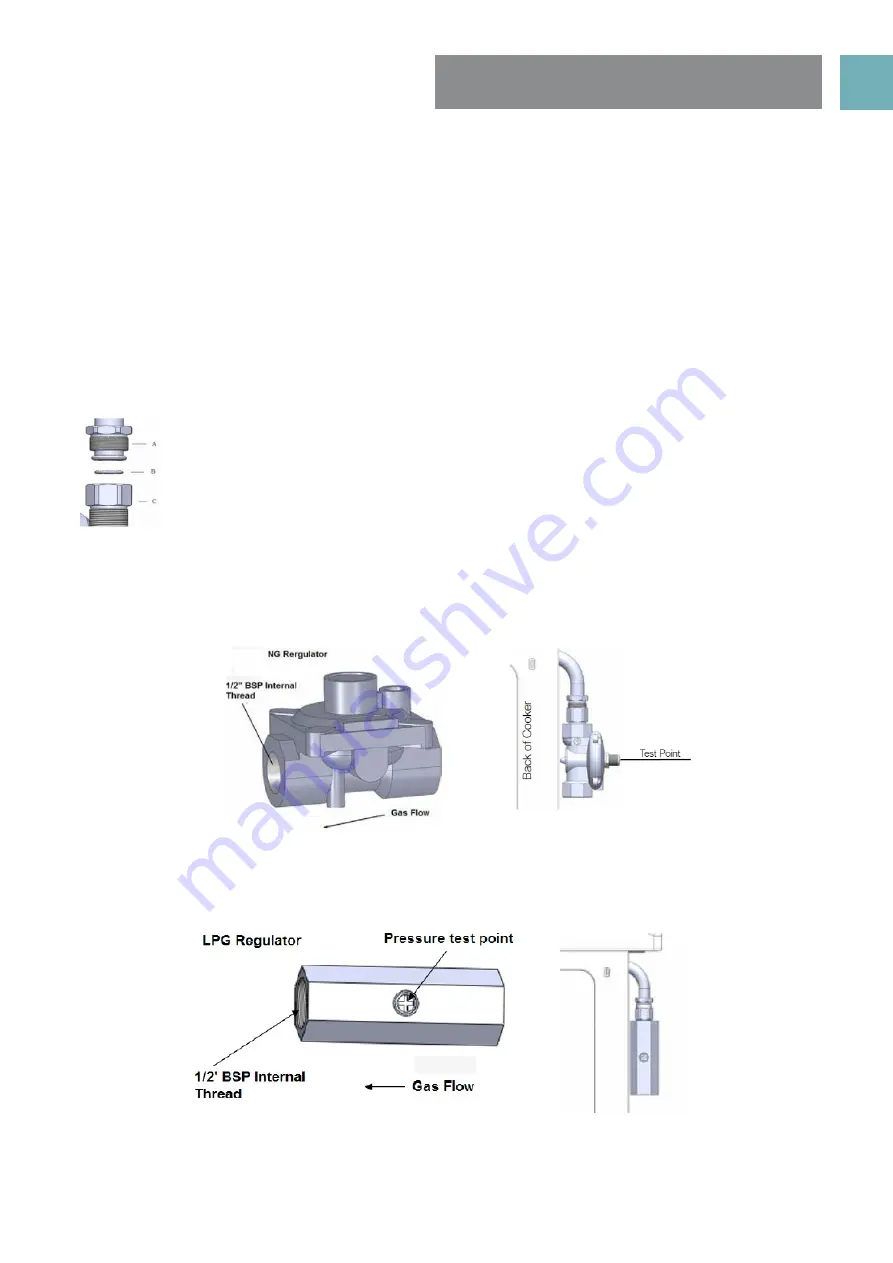
GAS CONNECTION
The gas inlet connection of the appliance has a “male thread.” When making the connection, take care
not to apply stresses of any kind to the appliance.
A
Inlet pipe joint
B Gasket
C
Stable
union
OPERATION ON NATURAL GAS
The supplied regulator must be fitted to the appliance inlet connection. Gas pressure must be adjusted to
1.0 kPa when the auxiliary, semi rapid and rapid burners are set to high flame, the appliance test point is
located on the regulator.
OPERATION ON UNIVERSAL LPG
The supplied test point adaptor must be fitted to the appliance inlet connection. Gas pressure must be
adjusted to 2.75 kPa, when the auxiliary, semi rapid and rapid burners are set to high flame, the appliance
test point is located on the test point adaptor.
When the installation is complete, always check that all the unions are absolutely tight using a soapy solution.
Never use a flame to make this check.
Summary of Contents for EFS54FC-DGS
Page 2: ......
Page 28: ...USER MANUAL PG 28 NOTES ...


