background image


REV.0.02_COD.500201_A4 


      PAG. 29 

6.  CONTROL PANEL AND SYMBOLS USED 

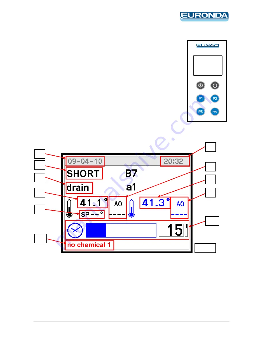
The control panel with liquid crystal display is illustrated in the diagram. 
This  panel  makes  the  machine  easy  to  use  as  it  indicates  the  stage  of  the  cycle  in 
progress, the maximum temperature reached during disinfection and fault messages. 


6.1  Control panel (loading side) 


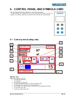
DISPLAY LCD 

Display the following information: 


The program selected (1). 


The phase (2). 


The date and time (3 and 4). 


The control temperature (5) and recording temperature (6). 


The temperature of set-point for the current phase (7). 


The A0 value for control temperature (8) and for the recording temperature (9). 


The remaining time (10). 


Any failure of the machine (11). 


10

11

PIC. 1 
Summary of Contents for Eurosafe 60

Page 1: ...Eurosafe 60 Instructions manual...

Page 2: ...Instructions manual Operating manual WASHER DISINFECTOR EUROSAFE 60 0051...

Page 3: ...2 Manufacturer STEELCO S p A Via Balegante 27 31039 Riese Pio X TV ITALIA Distributor EURONDA S p A Via dell Artigianato 7 Montecchio Precalcino VI Italy tel 39 0445 329811 fax 39 0445 865246 info eu...

Page 4: ...NECTION FOR THE INSTALLER ONLY 18 3 4 ELECTRICAL CONNECTION 19 3 5 FUSE 20 3 5 1 REPLACEMENT OF FUSE 20 3 6 CHEMICAL PRODUCTS CONNECTIONS 21 3 6 1 PRESENCE SENSOR OF CHEMICAL PRODUCT 21 3 6 2 METER QU...

Page 5: ...ION 48 12 1 2 CHECK 49 12 2 IMPULSED DOSING 50 12 2 1 CALIBRATION 50 12 2 2 CHECK 51 13 CLOCK 52 14 HISTORICAL DATA 52 15 ALARMS AND EVENTS LIST 53 15 1 LOGICAL DESCRIPTION OF ALARM INTERVENTIONS 53 1...

Page 6: ...performance of the appliance Following the instructions carefully The appliance was designed and constructed using the latest technological innovations available Please take good care of it Your sati...

Page 7: ...training course held by the manufacturer The instructions in this manual do not replace but rather are in addition to employer requirements to adhere to current legislation on standards of prevention...

Page 8: ...s Directive 2006 95 EC Low Voltage Directive 2014 30 EU EMC Electromagnetic compatibility directive EN 61010 1 Safety EN 61010 2 040 Safety and recognized international standards IEC 61000 Electromagn...

Page 9: ...ne intended is forbidden Improper use of this unit may be hazardous to the operator and may seriously damage the machine itself If the appliance is used in a manner not specified by the manufacturer p...

Page 10: ...authorised persons only This machine must be operated by trained persons only The machine must be used for treatment and thermo disinfection of instruments for orthodontic and medical use and for labo...

Page 11: ...e foreseen use only The machine was designed for use with water and chemical additives Do not use organic or other types of solvent as this may result in the risk of explosion or the rapid deteriorati...

Page 12: ...AL CONTAMINANTS Microbial contaminants can increase the microbial contamination of the instruments at the end of the wash The manufacturer therefore recommends that water used in the pre rinsing and w...

Page 13: ...ted skin areas immediately and rinse with water RISK Inhalation of vapours of chemical wash products MEASURE Assign staff that is instructed and equipped with appropriate clothing and individual prote...

Page 14: ...pertinent to this machine and most commonly used are Electrical risk Warning See annex documentation Caution hot surface INDIVIDUAL SAFETY WEAR The evaluation of risks for the health and safety of wo...

Page 15: ...ion and maintenance of the instructions concerning safety standards the actions to be avoided and the first aid interventions connected with use of the machine and the chemical wash agents it contains...

Page 16: ...overed herein and measured with an instrument at a height of 1 5 m at a distance of 1 m from the machine AVERAGE SOUND PRESSURE LEVEL 70 dB A 2 9 Transport and storage Environment conditions Temperatu...

Page 17: ...ng transport and lifting equipment and must be observed the following indications The lifting capability of the forklift must be greater than the total weight of the machine to be moved The machine mu...

Page 18: ...um load of 175 daN m 2 3 2 3 Positioning of the machine In normal conditions the minimum dimensions are suggested for the use of the machine in a single installation or with the coil nearby For differ...

Page 19: ...the correspondence of the connection of flexible tubes to the water supply taps arranged in site according to the references of the following chart CONNECTION COLOUR HOT WATER RED COLD WATER BLUE DEMI...

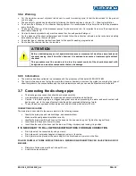
Page 20: ...ms are efficiently earthed The earth conductor is to be connected to the earth terminal identified by the standard symbol The machine is equipped with a terminal identified by the relative symbol for...

Page 21: ...sary contact our technical assistance service Replacement procedure of fuse Log off the machine in safety condition by dedicated safety device Access at the electrical panel Identify the fuse subjects...

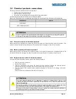
Page 22: ...the quantity measurement of dispensed product The electronic control system manages the value of required minimum quantity and if necessary stops the cycle 3 6 3 Replacement or refill of chemical pro...

Page 23: ...83 The type test was carried out using the most widely known chemical products on the market concerning the type of chemical products the concentrations and the cycle parameters used you can ask the M...

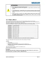
Page 24: ...softener when installed water hardness value must be introduced by entering into programmation PRG switch 5 seconds at parameter P7 26 and introduce one of the following values VALUE 10 NO REGENERATIO...

Page 25: ...ring the normal operation the machine warms up itself dispersing heat and hot air increasing the humidity value in the drying phase these events increase Therefore in order to guarantee a comfortable...

Page 26: ...iency of the emergency and machine shutdown devices circuit breaker Check the efficiency of the door opening safety micro switch Check the operation of machine controls especially the START and STOP c...

Page 27: ...an electric door lock to prevent it being opened when the machine is running To open the door during a wash cycle interrupt the cycle and remember that 1 The items inside the machine may be very hot...

Page 28: ...e washed inside the machine and position them carefully on the holder and in the rack Items should not overlap Receptacles should be positioned so that liquids can flow out easily Tall or heavy items...

Page 29: ...special accessories suitable for inserting the hand pieces These supports are made in two parts screwed together between which there is a special filter There is a rubber adaptor in the top part avail...

Page 30: ...re reached during disinfection and fault messages 6 1 Control panel loading side DISPLAY LCD Display the following information The program selected 1 The phase 2 The date and time 3 and 4 The control...

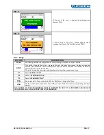
Page 31: ...o the setting of parameters P1 7 P1 8 P1 9 loading side P1 10 P1 11 P1 12 unloading side through which is possible to set its volume PIC 2 During the cycle by pressing the switch PRG it is possible to...

Page 32: ...displays a message indicating that disinfection did not take place keeps the door locked and if necessary indicates a high temperature inside the chamber To return the machine to normal conditions the...

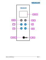
Page 33: ...REV 0 02_COD 500201_A4 PAG 32 P1 P2 P3 PRG START STOP DISPLAY ON OFF USB...

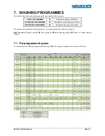
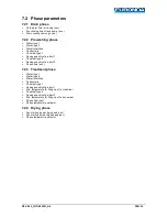
Page 34: ...or moderately soiled items INTENSIVE PROGRAMME P3 Suitable for heavily soiled items The machine has several washing programmes To enable programmes follow the procedure Enter the menu Program selectio...

Page 35: ...1 Chemical type 2 Dosing quantity of product 2 Phase time sec 7 2 3 Treatment phase Water type 1 Water type 2 Water total litres Conductivity Chemical type 1 Dosing quantity of product 1 Min temperatu...

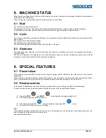
Page 36: ...ated on the display and the user interface is ready for the door release sequence and the Reset procedure to restore the machine to Wait see reset procedure 9 SPECIAL FEATURES 9 1 Power failure When t...

Page 37: ...r replacing mechanical parts e g drain pump etc on malfunctioning machines which have not completed the thermal disinfection cycle 10 3 Decontamination procedures When making repairs or replacing mech...

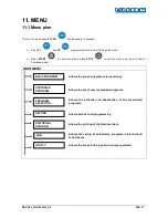
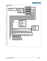
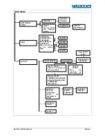
Page 38: ...Shutdown mode MAIN MENU CUSTOMER PROGRAM SETTING BASIC PROGRAM PROGRAM SELECTION UTILITY HISTORICAL PRINTING USB Allows the pre set programs view and copy Allows the set of new customized programs All...

Page 39: ...PARAMETERS COPY PHASE COPY SHOW PASSWORD CUSTOMER PROGRAMS PROGRAM SELECTION COPY MODIFY DELETE PASTE PHASE SELECTION MODIFIY PROGRAM NAME LIST OF PHASES PARAMETERS INSERT PHASE DELETE PHASE COPY PHAS...

Page 40: ...ENT 8 EQUIVALENCE PASSWORD PASSWORD PASSWORD PASSWORD 1 SET HOUR 2 SET MINUTES 3 SET DAY 4 SET MONTH 5 SET YEAR CALIBRATION Automatic calculation after the water or chemical loading at the quantity se...

Page 41: ...DIGITAL INPUTS TEMPERATURE PROBES ANALOG TRANSDUCER FLOWMETER DIP SWITCH SERVICE STATUS Information about the maintenance status WARNING SHOW PRINTING WARNING TIME SET WORKING HOUR HISTORICAL PRINT P...

Page 42: ...CTION PARAMETER DESCRIPTION MIN MAX UDM SYSTEM DATA MACHINE 1 1 User name 16 character CHAR_STR CYCLE 1 2 Operator identification 0 1 YES_NO PRINT OUT 1 4 Graphic print out at the end of the cycle 0 n...

Page 43: ...oth board 1 and 2 redundant print for machines that manage it 0 2 YES_NO CYCLE 3 4 Activate after cycle has been interrupted due to energy failure 0 when phase restarts 1 from the beginning of the cyc...

Page 44: ...n the chamber 0 999 SEC BOILER 6 2 Max time for 1 C increase in the boiler 0 999 SEC DRAINING 6 3 Maximum drainage time 0 999 SEC DRAINING 6 4 Maximum drainage time with rinsing water loaded 0 999 SEC...

Page 45: ...water in the chamber P7 07 99 LITRES CHAMBER 7 11 Max chamber probe temperature difference 0 99 DEGREE CHAMBER 7 12 Min temperature for max chamber temperature probes difference control 0 95 DEGREE D...

Page 46: ...11 Chemical product for dosing pump 3 sec millilitre timed control 0 9 999 SEC_mLT CHEMICALS 8 13 Way of dosing for chemical product1 0 by impulse 1 timed 0 1 MSG_DOSE_TYPE CHEMICALS 8 15 Way of dosin...

Page 47: ...ON It is also possible to activate every device but the electrical resistance manually Enter the menu UTILITY MAINTENANCE Insert 3 rd level password OUTPUT STATE Push P1 and P2 buttons to scroll the...

Page 48: ...haracter to be changed is flashing Pressing P1 and P2 buttons it is possible to set the value of character while pressing START button it is possible to confirm the selection and proceed with other ch...

Page 49: ...water 12 1 Timed dosing In order to do the chemicals calibration it is necessary to control that the chemical products dosing system is completely filled For this calibration s procedure it is necessa...

Page 50: ...eck that the level of product in the ml graduated cylinder is 100 ml or the same dosed in the previous calibration procedure If the level of dosed product is correct the check procedure is finished an...

Page 51: ...ATTENTION If it is not present the flowmeter the system displays the message FORBIDDEN Insert the suction lance of the chemical to be calibrated into a ml graduated cylinder and fill it with the chem...

Page 52: ...RT to begin the calibration verification Once finished the dosing the level of product in the ml graduated cylinder should be the same of that one shown in the display Chemical product Whether the lev...

Page 53: ...n the permanent memory The fields given in the example below are recorded for each cycle DATE START TIME PROGRAMME MAX C HOLD 85 C FAULTS 12 12 2012 12 00 Short 93 C 60 seconds 01 12 12 2012 13 05 Sta...

Page 54: ...block door the door has been opened 8 unblock door 2 Loading door problems c Overtime lock door ref P6 14 d During block door the door has been opened 9 unlocking 1fail Overtime unlock loading door r...

Page 55: ...impulses number superior to the threshold value set by parameter P7 21 with pump switched off 49 flowmeter fail 3 The flowmeter product 3 had counted an impulses number superior to the threshold valu...

Page 56: ...mp 3 is used up if it is set as a warning by P3 06 Diagnostics with dosing pump enabled Pressure switch state with pressure switch presence Lack of a new impulse after the time set by P6 12 if a flowm...

Page 57: ...tion allowing the selection between APPEND add only the new parts and OVERWRITE delete the existing files and install the new one It is possible to program Parameters Cycles Control panel FW Language...

Page 58: ...program are associated two files which contain the data structured as below The file G TXT contains N B the G TXT will be saved in automatically at the end of the washing program The file C TXT contai...

Page 59: ...t a z lowercase alphabet space minus sign full stop Operator denomination Length 16 can be empty Allowable characters 0 9 number digits A Z uppercase alphabet a z lowercase alphabet space minus sign f...

Page 60: ...ectant substances used see technical information for the product being used in compliance with standards concerning contact with parts of the machine which may be contaminated by pathogenic materials...

Page 61: ...G 60 TABLE OF ROUTINE MAINTENANCE TASKS N B Routine maintenance tasks must be performed at the intervals set forth in the table It is however advisable to carry out single cleaning tasks anytime you f...

Page 62: ...g levels To re start the appliance the fault that caused overheating must be corrected Every 12 months Clean the diaphragms of solenoid valves and replace if necessary Clean the thermostat probe Chang...

Page 63: ...it in position with the threaded pin Put the drain water filter group back in the wash chamber CLEANING OF WASHING CHAMBER THERMOSTAT PROBE M2 Worker Is Frequency of Intervention 6 months METHOD OF IN...

Page 64: ...rs and extract them from the chamber Unscrew the closure plug of the rear part of the nozzle and remove it Carefully cleaned and remove any incrustations from the washing rotor nozzles using appropria...

Page 65: ...THE MACHINE Worker Ac Frequency of Intervention every day METHOD OF CLEANING OUTER BODY Use a damp cloth to clean the outer body of the machine Use only neutral detergents Do not use abrasive detergen...

Page 66: ...e of special maintenance tasks See scheduled maintenance form table CLEANING OF COLDEATERINLETFILTERS M4 Worker Is Frequency of Intervention 6 months or when necessary METHOD OF INTERVENTION clean or...

Page 67: ...m filter as described below Remove the two screws from the drying system filter protective front panel and remove it from the machine Extract the filter and clean it of any dust If the filter is no lo...

Page 68: ...the drying system filter as described below Remove the two screws from the drying system filter protective front panel and remove it from the machine Extract the pre filter and than the HEPA filter re...

Page 69: ...e rotor 3 Extract the membrane pipe from the dispensing pump 4 Turn the rotor manually clockwise until the membrane pipe is fully extracted from the dispensing pump ATTENTION the rotor of dispensing p...

Page 70: ...mbrane tube attachments Turn the rotor manually clockwise until the membrane tube is fully extracted from the dispensing pump Apply an even layer of silicon grease to the membrane tube you have just r...

Page 71: ...OR THE SELECTED WASHING CYCLE C The thermostat probe of the washing chamber is dirty or covered with lime R Clean the thermostat probe of the washing chamber performing the routine maintenance describ...

Page 72: ...arrying out the routine maintenance set forth in chapter 18 Form M5 of this manual C The fan of the drying system does not work R Check the electrical connections of the drying system R Contact the Te...

Page 73: ...ith insulating covers to prevent rain or humidity from damaging the structure through oxidation or rust Following the legal requirements where the machine is installed and used dispose of all material...

Page 74: ...Aquafilter CDS301 CORAL ONYX EURONDA S p A Via dell Artigianato 7 36030 Montecchio Precalcino VI ITALY Tel 39 0445 329811 Fax 39 0445 865246 Internet www euronda com E mail info euronda com...

Reviews: