Hub van Doorneweg 8 • 2171 KZ Sassenheim – NL •
T
+31(0)252 228850 •
F
+31(0)252 228235 •
E
sales@euronorm.nl •
I
euronormdrives.com
Hub van Doorneweg 8 • 2171 KZ Sassenheim – NL •
T
+31(0)252 228850 •
F
+31(0)252 228235 •
E
sales@euronorm.nl •
I
euronormdrives.com
24
25
EURN010000_
002_C
EURN010000_
002_C
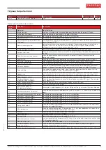
No. Fault ID
Failure type
Possible causes
Solutions
10
Err.10
Inverter overload
1. The type selection of inverter is small
2. Whether the load is too large or the motor stall occurs
1. Choose the inverter with large power level
2. Reduce the load and check the motor and its
mechanical conditions
11
Err.11
Motor Overload
1. Power grid voltage is too low
2. Whether the setting motor protection parameters
(F8.03) is appropriate or not
3. Whether the load is too large or the motor stall occurs
1. Check the power grid voltage
2. Correctly set this parameter.
3. Reduce the load and check the motor and its
mechanical conditions
13
Err.13
Output phase loss
1. The lead wires from the inverter to the motor is not
normal
2. The inverter’s three phase output is unbalanced when
the motor is running
3. The drive panel is abnormal.
4. The module is abnormal
1. Eliminate peripheral faults
2. Check the motor’s three-phase winding is normal
or not and eliminate faults
3. Seek for technical support
14
Err.14
Module overheating
1. The air duct is blocked
2. The fan is damaged
3. The ambient temperature is too high
4. The module thermistor is damaged
5. The inverter module is damaged
1. Clean up the air duct
2. Replace the fan
3. Decrease the ambient temperature
4. Replace the thermistor
5. Replace the inverter module
15
Err.15
External equipment
fault
Input external fault signal through the multi-function
terminal DI
Reset run
16
Err.16
Communication
fault
1. The communication cable is not normal
2. The settings for communication expansion card F9.07
are incorrect
3. The settings for communication parameters F9 group
are incorrect
4. The host computer is not working properly
1. Check the communication cable
2. Correctly set the communications expansion
card type
3. Correctly set the communication parameters
4. Check the wiring of host computer
17
Err.17
Contactor fault
1. Input phase loss
2. The drive plate and the contact are not normal
1. Check and eliminate the existing problems in the
peripheral line
2. replace the drive, the power board or contactor
18
Err.18
Current detection
fault
1. Check Hall device
2. The drive panel is abnormal.
1. Replace the drive panel
2. Replace hall device
19
Err.19
Motor parameter
auto tuning fault
1. The motor parameters was not set according to the
nameplate
2. The identification process of parameter is timeout
1. Correctly set motor parameter according to the
nameplate
2. Check the lead wire from the inverter to the
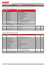
motor
21
Err.21
EEPROM read and
write fault
EEPROM chip is damaged
Replace the main control panel
22
Err.22
Inverter hardware
fault
1. Overvoltage
2. Overcurrent
1. Eliminate overvoltage fault
2. Eliminate overcurrent fault
23
Err.23
Short-circuit to
ground fault
Motor short to ground
Replace the cable or motor
26
Err.26
Cumulative running
time arrival fault
Cumulative running time arrival fault
Clear history information by using initialization
function parameters
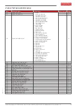
27
Err.27
Custom fault 1
Input custom fault 1 signal through the multi-function
terminal DI
Reset run
28
Err.28
Custom fault 2
Input custom fault 2 signal through the multi-function
terminal DI
Reset run
29
Err.29
Total power-on time
arrival fault
Total power-on time reaches the set value
Clear history information by using initialization
function parameters
31
Err.31
PID feedback loss
when running fault
PID feedback is less than the set value of E2.11
Check PID feedback signal or set E2.11 to an
appropriate value
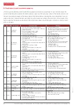
40
Err.40
Quick current
limiting fault
1. Whether the load is too large or the motor stall occurs
2. The type selection of inverter is small
1. Reduce the load and check the motor and its
mechanical conditions
2. Choose the inverter with large power level
42
Err.42
Too large speed
deviation fault
1. The setting for Too Large Speed Deviation
parameters(F8.15, F8.16) is unreasonable.
2. The setting for encoder parameters is incorrect;
3. The parameter was not identified
1. Reasonably set the detection parameters
2. Correctly set encoder parameters
3. Perform identification for the motor parameters
51
Err.51
Initial position error
The deviation between the motor parameters and the
actual parameters is too large
Reconfirm the correct motor parameters, focus on
whether the rated current is set to too small.


