Hub van Doorneweg 8 • 2171 KZ Sassenheim – NL •
T
+31(0)252 228850 •
F
+31(0)252 228235 •
E
sales@euronorm.nl •
I
euronormdrives.com
Hub van Doorneweg 8 • 2171 KZ Sassenheim – NL •
T
+31(0)252 228850 •
F
+31(0)252 228235 •
E
sales@euronorm.nl •
I
euronormdrives.com
18
19
NEURN030000_220_A
NEURN030000_220_A
6.2 Wiring Diagram
Frequency inverter wiring is divided by main circuit and control circuit. Users must properly connect frequency inverter in
accordance with the wiring connection diagram showing below.
6.2.1 Wiring diagram
Main circuit
Control circuit
Fig 4.3: Wiring diagram
6.3 Main circuit terminal
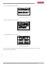
6.3.1 Main circuit terminal arrangement
1.
0.75~4kW G3 main circuit terminal (Moulded shell series)
R
S
T
+
RB
-
U
V
W
0.75~4kW G3 main circuit terminal
2.
5.5~11kW G3 main circuit terminal (Moulded shell series)
R
S
T
+
RB
-
U
V
W
P
5.5~11kW G3 main circuit terminal


