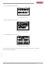
Hub van Doorneweg 8 • 2171 KZ Sassenheim – NL •
T
+31(0)252 228850 •
F
+31(0)252 228235 •
E
sales@euronorm.nl •
I
euronormdrives.com
24
25
NEURN030000_220_A
NEURN030000_220_A
6.4.3 Signal input terminal circuit
Switch input and output signal transmission, generally use the shielded cable and wiring short distance as far as possible,
good grounding and shielding layer on the inverter side, try not to over 20 m transmission distance. Drive in active way,
elected to the power of crosstalk necessary filtering measures are taken, generally recommend that choose dry contact
control mode.
Wiring control cable should be kept with the main circuit and high voltage lines (Such as the power cord, motor
connecting line, relay or contactor) more than 20 cm distance, and to avoid high voltage lines parallel to and can’t be
avoided and the high voltage lines cross, the proposal USES vertical wiring way, in order to prevent the misoperation
caused by disturbance frequency converter
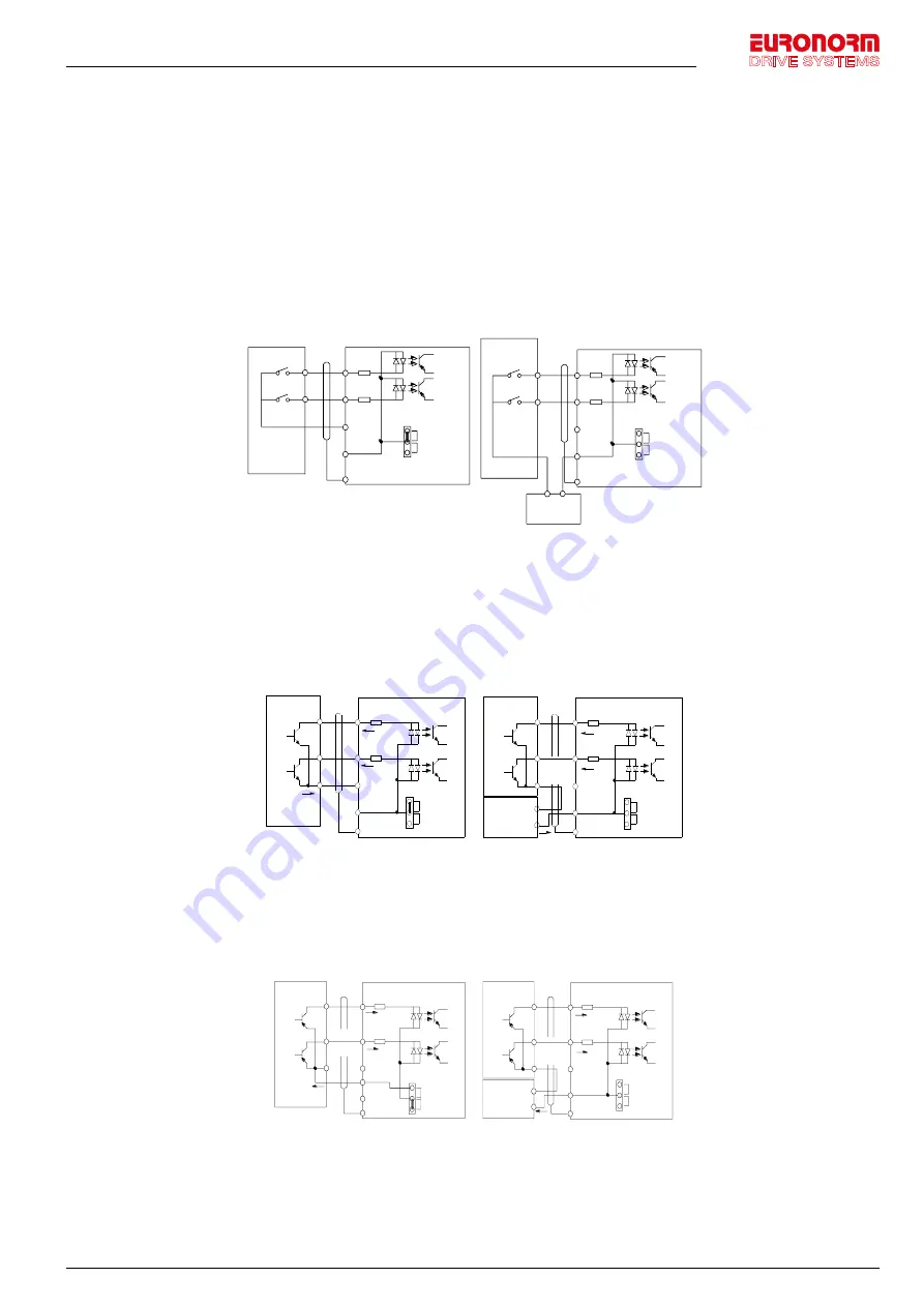
Dry contact mode:
Chapter 4 Installation and commissioning
47
Cha
pt
er 4
+24V
COM
PLC
(Default)
DI1
DI8
COM
PLC
PE
Shielded
cable
External
contactor
Inverter
Inner power supply with main connect
+24V
COM
PLC
(Default)
DI1
DI8
COM
PLC
PE
Shielded
cable
External
contactor
Inverter
External power supply
with main connection
External power
supply
+
-
Figure 4-19
:
Signal input terminal circuit- dry contact mode
Note: using an external power supply, PLC and 24 v jumper cap must be removed, otherwise it
will damage the product.
Open collector NPN connect wire:
When the input signal from the NPN transistor, according to the use of power supply, please
according to the 24 v and PLC jumper cap.
+24V
COM
PLC
(Default)
DI1
DI8
COM
PLC
PE
Shielded
cable
Inverter
Inner power NPN connect mode
External
contactor
+24V
COM
PLC
(Default)
DI1
DI8
COM
PLC
PE
Shielded
cable
Inverter
External power supply NPN connect mode
External
contactor
External
power supply
+
-
Figure 4-20
:
Signal input terminal wiring diagram, open collector NPN connection mode
Note: using an external power supply, PLC and 24 v jumper cap must be removed, otherwise
it will damage the product.
Open collector PNP connection mode:
Signal input terminal circuit- dry contact mode
Note:
using an external power supply, PLC and 24 v jumper cap must be removed, otherwise it will damage the product.
Open collector NPN connect wire:
When the input signal from the NPN transistor, according to the use of power supply, please
according to the 24 v
and PLC jumper cap.
Chapter 4 Installation and commissioning
47
Cha
pt
er 4
+24V
COM
PLC
(Default)
DI1
DI8
COM
PLC
PE
Shielded
cable
External
contactor
Inverter
Inner power supply with main connect
+24V
COM
PLC
(Default)
DI1
DI8
COM
PLC
PE
Shielded
cable
External
contactor
Inverter
External power supply
with main connection
External power
supply
+
-
Figure 4-19
:
Signal input terminal circuit- dry contact mode
Note: using an external power supply, PLC and 24 v jumper cap must be removed, otherwise it
will damage the product.
Open collector NPN connect wire:
When the input signal from the NPN transistor, according to the use of power supply, please
according to the 24 v and PLC jumper cap.
+24V
COM
PLC
(Default)
DI1
DI8
COM
PLC
PE
Shielded
cable
Inverter
Inner power NPN connect mode
External
contactor
+24V
COM
PLC
(Default)
DI1
DI8
COM
PLC
PE
Shielded
cable
Inverter
External power supply NPN connect mode
External
contactor
External
power supply
+
-
Figure 4-20
:
Signal input terminal wiring diagram, open collector NPN connection mode
Note: using an external power supply, PLC and 24 v jumper cap must be removed, otherwise
it will damage the product.
Open collector PNP connection mode:
Signal input terminal wiring diagram, open collector NPN connection mode
Note:
using an external power supply, PLC and 24 v jumper cap must be removed, otherwise it will damage the product.
Open collector PNP connection mode:
Chapter 4 Installation and commissioning
48
Cha
pt
er 4
+24V
COM
PLC
(Default)
DI1
DI8
COM
PLC
PE
Inverter
Inner power PNP connect mode
External
contactor
+24V
COM
PLC
(Default)
DI1
DI8
COM
PLC
PE
Shielded
cable
Inverter
External power supply PNP
connect mode
External
contactor
External
power supply
+
-
+24V
Figure 4-21
:
Signal input terminal wiring diagram, open collector PNP connection mode
Note: using an external power supply, PLC and 24 v jumper cap must be removed, otherwise
it will damage the product.
4-5.
Wiring Precautions
Danger
Make sure that the power switch is in the OFF state before wiring operation, or electrical
shock may occur!
Wiring must be performed by a professional trained personnel, or this may cause damage to
the equipment and personal injury!
Must be grounded firmly, otherwise there is a danger of electric shock or fire hazard !
Note
Make sure that the input power is consistent with the rated value of inverter, otherwise which
may cause damage to the inverter!
Make sure that the motor matches the inverter, otherwise which may cause damage to the
motor or activate the inverter protection!
Do not connect power supply to U, V, W terminals, otherwise which may cause damage to the
inverter!
Do not directly connect braking resistor to DC bus (P), (+) terminals, otherwise which may
cause a fire!
※
The U,V,W output end of inverter can not install phase advancing capacitor or RC
absorbing device. The inverter input power must be cut off when replacing the motor
※
Do not let metal chips or wire ends into inside the inverter when wiring, otherwise which
may cause malfunction to the inverter.
※
Disconnect motor or switch power-frequency power supply only when the inverter stops
output
※
In order to minimize the effects of electromagnetic interference, it is recommended that
a surge absorption device shall be installed additionally when electromagnetic contactor and
relay is closer from the inverter.
Signal input terminal wiring diagram, open collector PNP connection mode
Note:
using an external power supply, PLC and 24 v jumper cap must be removed, otherwise it will damage the product.


