Installation
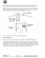
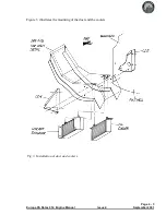
The throttle lever housing should be positioned such that its front face is 380 mm (15") aft of the
firewall. For the monowheel aircraft this will ensure clearance with the main wheel top when it is
retracted. Mark out and cut a slot for the throttle lever in the spine in the centre tunnel then,
checking that full throttle travel is achievable, drill through the flanges for mounting bolts.
For ease of installation attach an MS21047-3 anchor nut to the underside of the housing’s flange at
each end using TLPK 424 BS rivets then, using AN525-10R10 bolts, secure the housing in place.
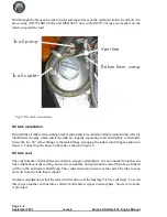
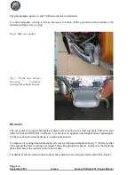
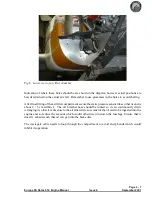
The front mounting will use an AN970-3 washer, see figure 2, and an AN970-3 washer can be used
temporarily to hold the rear of the mounting until it is substituted by the throttle closed stop.
Fit the throttle knob parts TH07 using an AN525-10R10 bolt and MS21042-3 nut to the top of the
throttle lever to complete the installation.
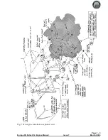
Slot the throttle cables through the gap between the firewall and the upper mounting members of the
landing gear frame, securing them to the frame with tie wraps to prevent chafing. Remove and
discard the straight cable-outer receptacle provided on each carburettor and in its place insert the
throttle cable’s threaded end. Use one check nut each side of the bracket to clamp the cable-outer in
place. The cables may seem excessively long, but this is to allow large bend radii in the engine bay to
ensure minimum friction.
Each throttle cable should emerge through the metal firewall on the opposite side to the carburettor
that it will control. Loop the cable up and aft towards the centre of the firewall, then down into the
bracket of the appropriate carburettor. Loosely secure the two cables where they cross.
Insert the cable inner into the nipple on the carburettor throttle lever, which is sprung to its full open
position. Setting the throttle lever in the cockpit back about 2-3 cm (1") from its full forward position,
screw both nipples tight on the cables. Check for full throttle movement, making any adjustments as
required, then seal the open hole in the throttle lever housing to prevent anything thrown up from the
wheel from entering.
Throttle closed stop
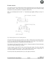
The addition of a throttle-closed stop is important to avoid the possibility of excess tension on the
throttle cable causing loss of throttle control. Following the method below, prepare a plate, made
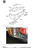
from 3 mm (1/8”) aluminium, 50 mm (2”) wide. With the throttle closed, and the slow running
adjustment correctly set at the carburettors, measure the distance from the rear of the throttle lever,
where it protrudes above the top of the tunnel, to the centre of the rear 4.8 mm (3/16”) mounting hole.
The plate length will be 6 mm (1/4”) more than this measurement. Drill the plate 6 mm (1/4”) from
one end, bond with Redux to the tunnel, and bolt with an AN525-10R10 bolt.
Note:
You should set the throttle closed stop such that a fully warmed engine idles at 1200 -
1400 rpm. Although the engine idles more smoothly at 1600 rpm or more, when landing the aircraft
you will benefit from minimal residual thrust.
Page 2 - 3
Europa XS Rotax 914 Engine Manual
Issue 9
April 2006
Summary of Contents for Rotax 914
Page 14: ...INTENTIONALLY BLANK Page 2 6 November 2007 Issue 10 Europa XS Rotax 914 Engine Manual ...
Page 28: ...Page 5 4 November 2004 Issue 8 Europa XS Rotax 914 Engine Manual Fig 2 Fuel system ...
Page 32: ...INTENTIONALLY BLANK Page 6 4 November 2004 Issue 8 Europa XS Rotax 914 Engine Manual ...
Page 40: ...INTENTIONALLY BLANK Page 8 6 September 2002 Issue 5 Europa XS Rotax 914 Engine Manual ...
Page 44: ...INTENTIONALLY BLANK Page 9 4 September 2002 Issue 5 Europa XS Rotax 914 Engine Manual ...

