Electric pumps to engine
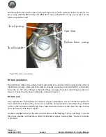
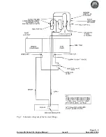
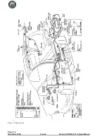
From the T piece after the electric fuel pumps to the engine use 8mm fuel hose. Route it forward
under the fuel tank and run it forward to emerge through the landing gear mount approximately 10
cm (4") below the top of the tunnel. Run the hose up the rear of the engine and connect it to the fuel
inlet fitting of the fuel pressure regulator. To protect against vapour locking, sleeve the hose forward
of the firewall with insulating fire sleeve and ensure that you don’t route the hose too close to
components which will be very hot, e.g. cooling system, exhaust, etc. Use hose clips to secure the
connections.
Fuel return line
From the return line fitting on the engine run a length of the 8mm fuel hose back to the fuel tank,
generally following the fuel supply line, but finishing at the starboard (reserve) fuel tank outlet.
Connect a union HFSB 8-2N to the unused port of the F09C fitting, and connect the return line to this
port. If your aircraft is fitted with the optional water drain kit, then you will need to fit a T piece
HFTP 8-8-8 into the line between the port tank outlet and the drain valve. The return line is then
fitted to this T piece.
Fuel sight gauge calibration
When the time comes to calibrate the fuel sight gauge you will need to start with the ‘Reserve’ side
full and only unuseable fuel in the ‘Main’ side. Set the aircraft level to simulate level flight then pour
in sufficient fuel to ensure that 2 or 3 litres will go over the tank tunnel and into the ‘Main’ side; 15
litres should be sufficient to do this. Remember that fuel enters the tank on the ‘Reserve’ side.
Now, ensure that the fuel selector valve is positioned to take fuel from the port side of the tank, which
is the ‘Main’ side and empty the port side of the tank only. Next, pour in fuel in equal quantities, 5
litres at a time for example. Mark off the gauge after each 5 litres has been added, bearing in mind
that, due to the tunnel in the tank and the variations in cross-section, the marks will not be equally
spaced.
Another point to consider is that, after the fuel has been used down below the top of the tunnel, the
sight gauge will indicate the level of the port side of the tank (main) only.
The fuel tank is designed to hold approximately 9 litres of reserve fuel. However, this amount may be
reduced in turbulent conditions. There will be a small quantity of unusable fuel.
Page 5 - 2
November 2004
Issue 8
Europa XS Rotax 914 Engine Manual
Summary of Contents for Rotax 914
Page 14: ...INTENTIONALLY BLANK Page 2 6 November 2007 Issue 10 Europa XS Rotax 914 Engine Manual ...
Page 28: ...Page 5 4 November 2004 Issue 8 Europa XS Rotax 914 Engine Manual Fig 2 Fuel system ...
Page 32: ...INTENTIONALLY BLANK Page 6 4 November 2004 Issue 8 Europa XS Rotax 914 Engine Manual ...
Page 40: ...INTENTIONALLY BLANK Page 8 6 September 2002 Issue 5 Europa XS Rotax 914 Engine Manual ...
Page 44: ...INTENTIONALLY BLANK Page 9 4 September 2002 Issue 5 Europa XS Rotax 914 Engine Manual ...

