Installation
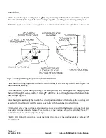
Mark a line on the upper cowling 13 mm (
1
2
“) away from and parallel to the “horizontal” edge. Mark
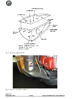
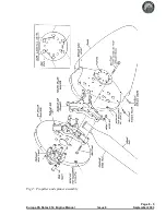
the centres for the holes to join the two cowlings together according to the drawing in figure 2.
Note:
The joint between the cowling halves is not horizontal with the aircraft datum waterline 0.
Place the two cowlings together and hold them with clamps or adhesive tape then try them in place on
the front of the fuselage.
Trim the bottom edge of the top cowling if necessary so that both cowlings can sit snugly in place
then drill through the centres with a 3.2 mm (
1
8
“) drill. Use clecos through some of the holes to hold
the cowlings together.
Since the engine has already been set to the correct position relative to the fuselage, the cowlings will
be set so that the front circular flat area is concentric with the engine propeller flange.
Trim the rear edge of the cowlings as required to ensure a good fit to the fuselage, with the front face
concentric with the propeller flange. The front face of the cowlings should be set to be 25mm (1”)
behind the front face of the propeller flange.
Finally, after fitting the cowlings, cut out the front circular face of the cowlings to leave a flange 25
mm (1") wide.
Page 6 - 2
November 2004
Issue 8
Europa XS Rotax 914 Engine Manual
Fig 2. Cowling trimming and position of attachment screws
Summary of Contents for Rotax 914
Page 14: ...INTENTIONALLY BLANK Page 2 6 November 2007 Issue 10 Europa XS Rotax 914 Engine Manual ...
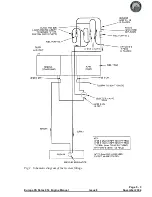
Page 28: ...Page 5 4 November 2004 Issue 8 Europa XS Rotax 914 Engine Manual Fig 2 Fuel system ...
Page 32: ...INTENTIONALLY BLANK Page 6 4 November 2004 Issue 8 Europa XS Rotax 914 Engine Manual ...
Page 40: ...INTENTIONALLY BLANK Page 8 6 September 2002 Issue 5 Europa XS Rotax 914 Engine Manual ...
Page 44: ...INTENTIONALLY BLANK Page 9 4 September 2002 Issue 5 Europa XS Rotax 914 Engine Manual ...

