8. Propeller and spinner
This chapter relates to the fitting of the Warp Drive ground adjustable propeller. If other ground
adjustable propellers are fitted, the general instructions in this chapter will apply, but details will
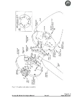
vary. Refer to the figure showing the propeller and spinner arrangement at the end of this chapter.
Spinner bulkheads
Rear bulkhead
Carefully mark out and drill with a hole saw six holes in the rear bulkhead, concentric with the
periphery, to allow through the propeller drive lugs which you have installed in the engine propeller
shaft flange. Cut out also the central hole required for the boss in the propeller flange. Make these
holes such that the bulkhead is not loose on the lugs and centre boss.
Front bulkhead
Mark out and drill six holes in the front bulkhead, concentric with the periphery, to allow through the
propeller attachment bolts.
Also make holes in the front bulkhead, centred on where each of the propeller blade clamping bolts
will be, to allow a suitably sized socket through with some clearance.
Drill through the head of each propeller attachment bolt to allow locking wire to be used.
Propeller
Make up the propeller according to the manufacturer’s instructions, setting the blade angles only
approximately at this stage. Fine setting of blade angle is best done on the aircraft. Tighten the bolts
according to the manufacturers specification.
File the front bulkhead flange locally to clear each propeller blade, then bolt the propeller to the
engine propeller flange with the bulkheads either side of the propeller hub, and the face plate against
the front bulkhead. Tighten these bolts according to the manufacturer’s specification. Mark both
bulkheads and the propeller flange to note their relative positions for later reference.
Spinner
Cut away sufficient of the rear edge of the spinner in the three positions where the propeller blades
are to allow the spinner’s rear edge to align with the rear bulkhead flange. Allow a clearance of about
3-4mm (1/8") around the blades.
Although it’s a good starting point, don’t rely on the alignment of the flanges of the spinner and rear
bulkhead to ensure the spinner is true.
Page 8 - 1
Europa XS Rotax 914 Engine Manual
Issue 4
September 2001
Summary of Contents for Rotax 914
Page 14: ...INTENTIONALLY BLANK Page 2 6 November 2007 Issue 10 Europa XS Rotax 914 Engine Manual ...
Page 28: ...Page 5 4 November 2004 Issue 8 Europa XS Rotax 914 Engine Manual Fig 2 Fuel system ...
Page 32: ...INTENTIONALLY BLANK Page 6 4 November 2004 Issue 8 Europa XS Rotax 914 Engine Manual ...
Page 40: ...INTENTIONALLY BLANK Page 8 6 September 2002 Issue 5 Europa XS Rotax 914 Engine Manual ...
Page 44: ...INTENTIONALLY BLANK Page 9 4 September 2002 Issue 5 Europa XS Rotax 914 Engine Manual ...

