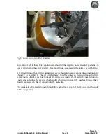
Measure the angle that the aircraft is sitting by using the inclinometer, which is provided with the
Warp Drive propeller, on the port side door rebate and make a note of it. This angle will have to be
added to the angle measured at the blade tip to give the actual blade pitch angle required.
For example; if a blade angle of 21
o
is required and the aircraft deck angle is 7
o
you should set the
blade to an angle of 14
o
from the vertical.
The vernier scale enables accurate measurement of angles to within 5 minutes of arc. A description
of how to use it is included later.
Adjusting method
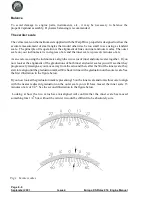
Set the propeller blade that is to be adjusted horizontal, with the leading edge uppermost, checking
this with a spirit level.
Clamp the inclinometer to the back of the blade tip.
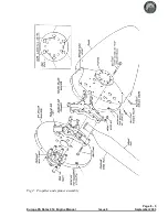
Slacken off the four blade clamping bolts and the four closest propeller hub securing bolts. It should
now be possible to rotate the blade to the desired angle. Ensure that the blade is fully pulled out
against the stops in the hub, as there is some radial movement available; if this is not done the
propeller balance will be degraded.
Once the blade angle is set, tighten the bolts, 20 inch pounds at a time, starting with the bolts nearest
the centre and working outwards. After tightening the bolts, check that the blade angle setting has not
altered.
Turn the propeller to the next blade and repeat the sequence.
After the last blade has been set, check that the others have not been disturbed. Don’t accept a
mismatch between blades of an angle any more than 15 minutes. Having satisfied yourself that the
blades are within acceptable limits, wirelock the six propeller securing bolts in pairs. See the inset
diagram in the main figure.
Run the engine to check that the desired static R.P.M. is achieved then install the spinner, checking it
for concentricity.
Warning :
It is imperative that special care is taken in the attachment of the spinner. If it is not
securely fastened and departs the aircraft in flight it
will
destroy the propeller which could result in
failure of the engine mounting.
Because the propeller is delivered disassembled and because there will be small variations between
individual spinners, it is important that the propeller/spinner combination is dynamically balanced.
This operation is normally carried out by specialists who have the requisite equipment and expertise.
Page 8 - 3
Europa XS Rotax 914 Engine Manual
Issue 4
September 2001
Summary of Contents for Rotax 914
Page 14: ...INTENTIONALLY BLANK Page 2 6 November 2007 Issue 10 Europa XS Rotax 914 Engine Manual ...
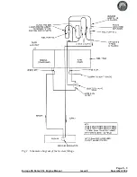
Page 28: ...Page 5 4 November 2004 Issue 8 Europa XS Rotax 914 Engine Manual Fig 2 Fuel system ...
Page 32: ...INTENTIONALLY BLANK Page 6 4 November 2004 Issue 8 Europa XS Rotax 914 Engine Manual ...
Page 40: ...INTENTIONALLY BLANK Page 8 6 September 2002 Issue 5 Europa XS Rotax 914 Engine Manual ...
Page 44: ...INTENTIONALLY BLANK Page 9 4 September 2002 Issue 5 Europa XS Rotax 914 Engine Manual ...

