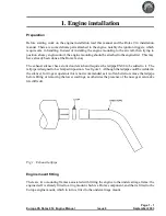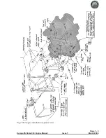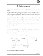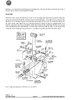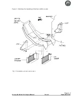
Fit the engine mounting frame to the Rotax ring mount using M10 x 110 bolts and M10 Binx nuts.
The upper bolts and the lower port bolt should be fitted with the bolt heads aft, and the lower
starboard bolt with the head forward. The excess length of the bolts will need to be cut off, leaving a
minimum of two threads emerging from the end of the nut. It will be necessary to chamfer the lower
starboard bolt’s head as shown in figure 2.
Engine installation
Mount the engine to the landing gear frame using the rubber mountings. See figure 2
To check the orientation of the engine, set the fuselage level using the port door sill as the reference as
usual. Check that the propeller flange is truly vertical.
The engine mounting frame has been designed with the engine offset to starboard by 1.5° To check
that this offset is correct clamp a straight edge to the propeller flange horizontally and mark a point
51 cm (20") each side of the engine centre line. Measure the distance from these points, parallel to the
aircraft centre line, to the firewall. The difference between the two readings should be 26 mm
(1-1/16"). If any correction is found necessary, shim between the landing gear frame and the
appropriate cup washer using AN960-516L washers. In order to ensure that the split pin is correctly
positioned relative to the castellated nut it will be necessary to use a total of at least 4 washers on each
bolt. Any washers that are not needed to act as positioning shims should be placed immediately
under the nut. Make a note of where and how many shim washers are used for later reference.
Note:
The 4 AN5-41 mounting bolts must be tightened fully to compress the rubber anti-vibration
mounts (MT04) onto the steel spacers (MT03).
Caution
:
It should be noted that before the two ignition leads which come from the ignition box are
earthed, the ignition is ”live”. Even though the engine speed must be at least 1200 rpm for the
ignition to fire, it would be a sensible precaution to fit the magneto switches before further work is
carried out on the engine, or at least temporary earth leads connecting the ignition wires to the
engine casing.
Wastegate control
The turbocharger wastegate is controlled by the TCU and operated by the servo motor unit. These
two items have to be positioned away from sources of high temperatures. Consequently they are to
be fitted in the cabin on the top of the tunnel right at the front behind the firewall.
Servo motor
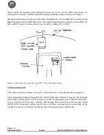
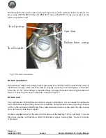
The servo motor is mounted horizontally on the right of the tunnel, with the operating cable facing
forwards. The positions shown in figure 3 are suggested but, depending on the equipment in the
instrument panel, you may have to site them elsewhere.
Be careful to take into account the length of the already made up cables which connect the various
engine related components together before making your final decision on their positions.
Page 1 - 2
June 2004
Issue 7
Europa XS Rotax 914 Engine Manual
Summary of Contents for Rotax 914
Page 14: ...INTENTIONALLY BLANK Page 2 6 November 2007 Issue 10 Europa XS Rotax 914 Engine Manual ...
Page 28: ...Page 5 4 November 2004 Issue 8 Europa XS Rotax 914 Engine Manual Fig 2 Fuel system ...
Page 32: ...INTENTIONALLY BLANK Page 6 4 November 2004 Issue 8 Europa XS Rotax 914 Engine Manual ...
Page 40: ...INTENTIONALLY BLANK Page 8 6 September 2002 Issue 5 Europa XS Rotax 914 Engine Manual ...
Page 44: ...INTENTIONALLY BLANK Page 9 4 September 2002 Issue 5 Europa XS Rotax 914 Engine Manual ...

