Pressure sensors
Two pressure sensors are provided with the engine, measuring respectively the static pressure and
the airbox pressure. These sensors need to be mounted with the pressure connection facing
downwards, to avoid any possibility of condensate entering them.
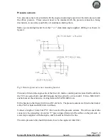
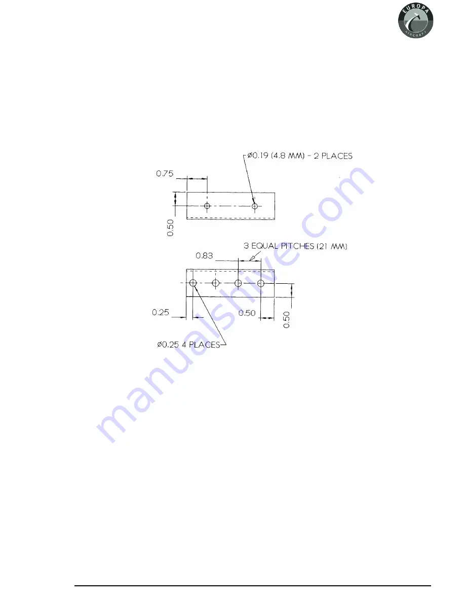
Make up a mounting bracket from the 1" x 1" aluminium angle supplied, drilling it as shown in
figure 4.
This unit is fitted on the engine side of the firewall - mark a suitable position (note that the cables to
the TCU are quite short), and drill through the firewall with a 4.8 mm drill. Fit two MS21047-3
anchor nuts on the cabin side, riveting them with TAPK36BS rivets.
Fit the bracket to the firewall with two AN3-4A bolts. The pressure sensors are fitted to the bracket
with AN4-5A bolts and MS21042-4 stiffnuts.
Connect a length of 4 mm bore PVC tube to each of the pressure sensors. The airbox sensor tube
connects to the unused leg of a nylon “T” piece situated forward of the airbox on the port side. A
water trap is supplied with the engine, and it should be fitted in the line.
The static pressure tube should terminate close to the engine air inlet filter.
Page 1 - 5
Europa XS Rotax 914 Engine Manual
Issue 6
September 2003
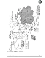
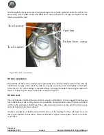
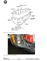
Fig 3. Detail of pressure sensor mounting bracket.
Summary of Contents for Rotax 914
Page 14: ...INTENTIONALLY BLANK Page 2 6 November 2007 Issue 10 Europa XS Rotax 914 Engine Manual ...
Page 28: ...Page 5 4 November 2004 Issue 8 Europa XS Rotax 914 Engine Manual Fig 2 Fuel system ...
Page 32: ...INTENTIONALLY BLANK Page 6 4 November 2004 Issue 8 Europa XS Rotax 914 Engine Manual ...
Page 40: ...INTENTIONALLY BLANK Page 8 6 September 2002 Issue 5 Europa XS Rotax 914 Engine Manual ...
Page 44: ...INTENTIONALLY BLANK Page 9 4 September 2002 Issue 5 Europa XS Rotax 914 Engine Manual ...

