5
5.
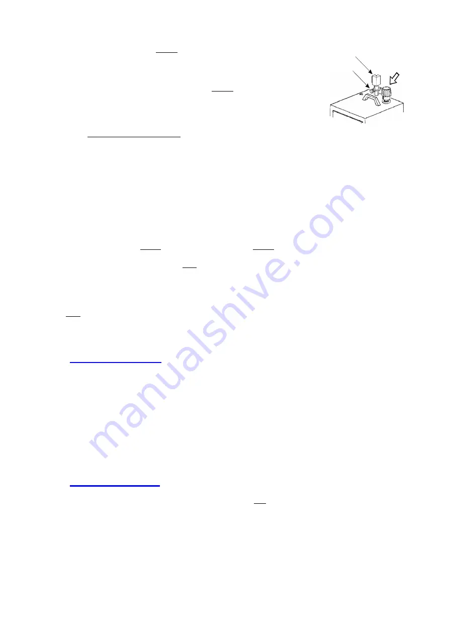
Open Safety Water Cap (Fig. 3) by pushing down and turning
counter-clockwise.
6.
Fill the boiler with water to the desired level, not to exceed
MAX level marked on the sight glass. (Fig. 2) Do not over-
fill.
Note: Do not use distilled water.
7.
Close the water cap by pressing down and turning clockwise. Do not overtighten.
8.
For floor type models (EVG-353, 354, 367 and 368), see Fig. 4 to make sure the drain valve of
the boiler is closed.
9.
Plug boiler into grounded outlet of sufficient power (110/120 Volts, see Specifications Chart
above for amperage)
10.
Turn on iron switch (Fig. 2, “D”) and boiler switch (Fig. 2, “C”). Both switches will light up.
11.
Set thermostat knob on the iron (Fig. 5) to desired temperature. These temperature settings are
approximate. Always check temperature on a hidden part of garment. The setting for steam is
“Cotton” (“
∙∙∙
”) or higher.
12.
When the pressure gauge reads approximately 40 PSI and the boiler lamp is turned off
(Fig. 2, “A”), you are ready to press. During ironing this light will go on and off and the
pressure gauge needle will move up and down. This is normal operating function.
B.
USING IRON/BOILER
1.
To get steam, press the thumb switch (microswitch) on the iron. (Fig. 6).
2.
At the beginning of each pressing session, point the iron away from the garment, in a safe
direction, and press the thumb switch on the iron to eliminate any condensate from the iron.
3.
The volume of steam can be controlled by turning the flow control knob (knob for steam
adjustment) (Fig. 3) on the solenoid valve. (normal position is half-open).
4.
When finished pressing, turn off the boiler and iron switches and unplug the boiler.
C.
REFILLING BOILER
When water level is at the bottom of the sight glass (Fig 2
)
, refill the boiler.
Before refilling
the boiler, it is important to release steam to make sure that the boiler is not under
pressure.
See details below.
Fig. 3
SOLENOID
VALVE
KNOB FOR
STEAM
ADJUSTMENT
SAFETY
WATER CAP
Summary of Contents for Hi-Steam EVG-35 Series
Page 10: ...10 ...
Page 20: ...20 ...
Page 21: ...21 ...
Page 24: ...24 ...
Page 26: ...26 EVG 36 Series Boiler Wiring Diagram Schéma de câblage de la chaudière série EVG 36 ...
Page 27: ...27 Electric Iron Diagram Schéma électrique du fer à repasser ...


