background image

Page 27

DV 42 Indoor Gas Fireplace

Appendix

Appendix C: State of Massachusetts

Amendment

 (Gas Fireplace / Equipment sold in the State of Massachusetts)
 5.08: Modifications to NFPA-54, Chapter 10
 

(1) Revise NFPA-54 section 10.5.4.2 by adding a second exception as follows:

Existing chimneys shall be permitted to have their use continued when a gas conversion burner is installed, and shall be equipped with a manually reset device that will automatically shut off 
the gas to the burner in the event of a sustained back-draft.
 

(2) Revise 10.8.3 by adding the following additional requirements:

(a) For all side wall horizontally vented gas fueled equipment installed in every dwelling, building or structure used in whole or in part for residential purposes, including those owned or 
operated by the Commonwealth and where the side wall exhaust vent termination is less than seven (7) feet above finished grade in the area of the venting, including but not limited to decks 
and porches, the following requirements shall be satisfied: 
 

1. INSTALLATION OF CARBON MONOXIDE DETECTORS. At the time of installation of the side wall horizontal vented gas fueled equipment, the installing plumber or gas fitter shall observe 

that a hard wired carbon monoxide detector with an alarm and battery back-up is installed on the floor level where the gas equipment is to be installed. In addition, the installing plumber or 
gas fitter shall observe that a battery operated or hard wired carbon monoxide detector with an alarm is installed on each additional level of the dwelling, building or structure served by the 
side wall horizontal vented gas fueled equipment. It shall be the responsibility of the property owner to secure the services of qualified licensed professionals for the installation of hard wired 
carbon monoxide detectors
a. In the event that the side wall horizontally vented gas fueled equipment is installed in a crawl space or an attic, the hard wired carbon monoxide detector with alarm and battery back-up 
may be installed on the next adjacent floor level.
b. In the event that the requirements of this subdivision can not be met at the time of completion of installation, the owner shall have a period of thirty (30) days to comply with the above 
requirements; provided, however, that during said thirty (30) day period, a battery operated carbon monoxide detector with an alarm shall be installed.
 

2. APPROVED CARBON MONOXIDE DETECTORS. Each carbon monoxide detector as required in accordance with the above provisions shall comply with NFPA 720 and be ANSI/UL 2034 listed 

and IAS certified. 
 

3. SIGNAGE. A metal or plastic identification plate shall be permanently mounted to the exterior of the building at a minimum height of eight (8) feet above grade directly in line with 

the exhaust vent terminal for the horizontally vented gas fueled heating appliance or equipment. The sign shall read, in print size no less than one-half (1/2) inch in size, “GAS VENT DIRECTLY 
BELOW. KEEP CLEAR OF ALL OBSTRUCTIONS”.
 

4. INSPECTION. The state or local gas inspector of the side wall horizontally vented gas fueled equipment shall not approve the installation unless, upon inspection, the inspector observes 

carbon monoxide detectors and signage installed in accordance with the provisions of 248 CMR 5.08(2)(a)1 through 4. 
(b) EXEMPTIONS: The following equipment is exempt from 248 CMR 5.08(2)(a)1 through 4: 
 

1. The equipment listed in Chapter 10 entitled “Equipment Not Required To Be Vented” in the most current edition of NFPA 54 as adopted by the Board; and 


2. Product Approved side wall horizontally vented gas fueled equipment installed in a room or structure separate from the dwelling, building or structure used in whole or in part for 

residential purposes.  
 

(c) MANUFACTURER REQUIREMENTS - GAS EQUIPMENT VENTING SYSTEM PROVIDED. When the manufacturer of Product Approved side wall horizontally vented gas equipment provides a 

venting system design or venting system components with the equipment, the instructions provided by the manufacturer for installation of the equipment and the venting system shall include:
 

1. Detailed instructions for the installation of the venting system design or the venting system components; and


2. A complete parts list for the venting system design or venting system. 


(d) MANUFACTURER REQUIREMENTS - GAS EQUIPMENT VENTING SYSTEM NOT PROVIDED. When the manufacturer of a Product Approved side wall horizontally vented gas fueled equipment 

does not provide the parts for venting the flue gases, but identifies “special venting systems”, the following requirements shall be satisfied by the manufacturer:
 

1. The referenced “special venting system” instructions shall be included with the appliance or equipment installation instructions; 


2. The “special venting systems” shall be Product Approved by the Board, and the instructions for that system shall include a parts list and detailed installation instructions. 

(e) A copy of all installation instructions for all Product Approved side wall horizontally vented gas fueled equipment, all venting instructions, all parts lists for venting instructions, and/or all 
venting design instructions shall remain with the appliance or equipment at the completion of the installation.
 

(3) After NFPA-54 section 10.10.4.2 add a new section 10.10.4.3 as follows:

When more than four gas appliances are to be vented through a common gas vent or common horizontal vent manifold, a plan of the proposed vent installation shall be submitted to the Inspector 
and the serving gas supplier for review and approval.

Extraction from: Massachusetts Rules and Regulations
5.00: Amendments To 2002 Edition Of ANSI Z223.1-NFPA-54

Summary of Contents for DV 42

Page 1: ...anger for cutter Entrapment hazard Battery hazard Rotating parts Low temperature Strong magnetic field Optical radiation Non ionizing radiation Radiation Hazardous to the Environment Danger of harming your hands Irritant Cutting Watch your step Slippery floor High temperatures Glass hazard Danger of suffocation High voltage Toxic Flammable materials Corrosive Fork lift trucks Danger overhead crane...

Page 2: ... 11 Top Vent Wall mounted termination one elbow 11 Top Vent Wall mounted termination multi elbow 11 Top Vent Wall mounted termination 45 corner 12 Top Vent Wall mounted termination 45 corner 12 Rear Vent Wall mounted Termination Graph 13 Standard Rear Vent no elbows or offsets 13 Rear Vent Wall mounted termination two elbows 13 Section 3 3 2 Venting Components 14 Section 3 3 3 Heat Shields 15 Inst...

Page 3: ...g body where the fireplace is being installed This installation operation and maintenance manual is applicabletothemodelsdescribedbelow Refertoyourrating plate to verify included options TheEuropeanHomewarrantywillbevoidedby andEuropean Home disclaims any responsibility for the following actions Modification of the fireplace and or components including direct vent assembly or glass doors Use of an...

Page 4: ...6 XW2018 Due to high operating temperatures this appliance should be located out of traffic away from furniture and draperies Children and adults should be alerted to the hazards of the high surface temperature which could cause burns or clothing ignition Young children should be carefully supervised when they are in the same room as the appliance Clothing or other flammable materials should not b...

Page 5: ...y be installed in any location that maintainsproperclearancestoairconditioningducts electrical wiringandplumbing Safety aswellasefficiencyofoperation shouldbeconsideredwhenselectingthefireplacelocation Try toselectalocationthatdoesnotinterferewithroomtraffic has adequate ventilation and offers an accessible path for direct vent installation The fireplace dimensions are shown below 6 5 19 Opening 3...

Page 6: ...e fireplace top vent Figure 4 Combustible framing for rear vent with shelf above the fireplace Figure 3 Combustible framing for top vent with shelf above fireplace European Home supplies a variety of direct venting and termination options The direct vent termination location MUSTbeselectedsuchthatitisthehighestpointintheventing assembly It should also be selected such that it provides the shortest...

Page 7: ... refer to the appropriate section below for installation details All fireplaces shipped from the factory are top vent See Section 3 1 for converting the unit from top vent to rear vent Figure 6 CombustibleFramingSideHeatShield twopieces Framing Heat Shield Included with the DV 42 Gas fireplace is a framing heat shield kit This kit is fabricated from galvanized steel and arrives with three pieces a...

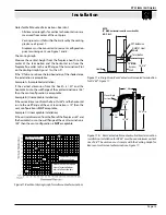
Page 8: ...ir inlet Termination location must be a minimum 18 from a parapet wall A maximum of two offsets each offset is made up of two 90 bends may be made Install a firestop at any location where venting passes through combustible materials and construction Utilize support straps or support plates and rings as required to meet acceptable building practices Install all roof flashing and storm collars as sh...

Page 9: ...of vent runs and 2 above horizontal vent runs to any combustible material Ensurewhencuttingsectionsofrigidpipetomaintain integrity of internal supports Place the springs supplied with the pipe kit between the outer and inner pipes to keep the pipes separate and avoid any possible hot spots EuropeanHomerecommendstheuseofaflexsection for the final pipe connected directly to the fireplace offeringgre...

Page 10: ... the BSR opening to 12 x 12 2 Secure the BSR frame to the exterior sheathing of the structure 3 FastentheterminationtotheBSRframeusingaminimumof4screws 1 Frame the MOSR opening to 12 x 12 2 FastentheMOSRframetotheinteriorsideofthestuds concrete or finished wall construction using a minimum of 4 screws 3 Insert the termination into the MOSR frame as shown here from the inside and attach to the MOSR...

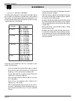
Page 11: ... one 90 bend The vent run must comply with Venting Graph for Top Vent wall mounted terminations Figure 14 Figure16a TopVented wallmountedmulti elbowinstallation See VentingGraphforTopVent wallmountedterminations Figure14 Important Aninspectionoftheexplosionreliefflappersanddoormust be made prior to lighting the fireplace This will ensure the door gasket material will provide an adequate seal durin...

Page 12: ...on 45 or less Corner Installation Use an PTO 4 termination and an PFL 1 or PFL 2 PFL 2 12 or 24 compressed length and a frame if appropriate Flex may be turned to obtain desired degree of angle required but must not exceed 45 Note A wall venting kits is available for both the straight and the corner installation The kit includes a heat shield a PXT 12 and a termination with a mounting frame PEL 45...

Page 13: ...cceptable Example A Acceptable Installation If the vertical dimension from the hearth is 120 and the horizontalruntothewallflangeoftheventterminationis138 then the vent configuration is acceptable Example B Unacceptable Installation Iftheverticaldimensionfromthehearthis48 andthehorizontal run to the wall flange of the vent termination is 72 then the vent configuration is NOT acceptable Example C U...

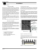
Page 14: ...n European Home parts will void the warranty and may impede operation of the fireplace Use any combination of rigid and flex pipe as required Flex sections may be stretched up to 50 of their total length e g a 24 section maybe stretched to 36 Connectallventsectionsusingaminimumofthreesheet metal screws on the outer pipe flue Ensure the pipe ends male to female slide in a minimum of 11 2 of overlap...

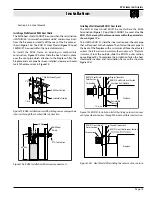
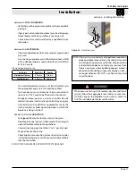
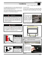
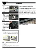
Page 15: ...ng the outer section in place Termination Drywall sheetrock RHS101 Heat Shield inner Section RHS101 Heat Shield Outer Section Fireplace Installing aWall Mounted RHS101 Heat shield The RHS101 Heat shield MUST be used where the RHS8 Termination Figure 19 and 19a CANNOT be used Use the RHS101whereanyofthedimensionsarewithintheparameters shown Figure 19a To install the RHS101 slide the inner section o...

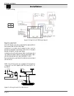
Page 16: ...C22 1 Canadian Electrical Code Part 1 and or Local Codes InstallationsintheUSAwhichemploythefansmustbegrounded inaccordancewithlocalcodesor intheabsenceoflocalcodes with the National Electrical Code ANSI NFPA 70 1987 FormoreinformationseetheFanKitInstallationGuideincluded with the fan kit NOTE If any of the original wire supplied with the appliance is replaced it must be replaced with the same typ...

Page 17: ...performancerequiresproperinput pressures Gas line sizing requirements will be determined in ANSI Z221 3 National Fuel Gas Code in the USA and CAN CGA B149 in Canada Pressure requirements are Gas Pressure Natural Gas Propane Minimum inlet pressure 5 5in w c 11in w c Manifold pressure 3 5in w c 10in w c The manifold outlet pressure is set from the factory to the appropriate pressure but should be ve...

Page 18: ...mbustible Materials that can catch fire and burn are considered combustible Anymaterialthatismadeof orfacedwith wood wood pulp paper plastic or any other material that can catch fire and burn is considered combustible Even though these materials may have been flame proofed made fire resistant or are fire rated they are considered combustible The combustibility of a material can be tested per ASTM ...

Page 19: ...Figure 26b Door Buckle Tool 1 Step 4 Firmlygrasphand hold end of door buckle tool andplacethemachined end in the slot under door frame as shown Figure 26c Step 2 Step 3 Step 1 Removethehorizontalcover by placing fingers in both finger holes then pushing away from you and lifting out Place it aside during maintenance or cleaning Install in reverse order Installed Gas Valve Cover Finger Holes The su...

Page 20: ...r hook the top edge of the door frame into place Lower the door into position and follow the previous steps shown in reverse order Installing the Door 2 Step 5 Ensure the tool is firmly in the lower end of the slot as shown then pull toward you CAUTION Hold the tool securely 3 Step 6 Pull hard if necessary to release the spring tension CAUTION The latch springs back with force hold the tool secure...

Page 21: ...rizontal access panel withContinuous Pilot withAmericanFlameElectronicIgnition For Your Safety READ BEFORE LIGHTING WARNING If you do not follow these instructions exactly a fire or explosion may result causing property damage personal injury or loss of life Lighting Instructions 1 STOP Read the safety information above on this label 2 Lift out the lower horizontal access panel 3 Pushingascontrolk...

Page 22: ...cause some gas is heavier than air and will settle on the floor What To Do If You Smell Gas Do not try to light any appliance Donottouchanyelectricalswitch donotuseanyphone in your building Immediately call your gas supplier from a neighbor s 1 STOP Read the safety information above on this label 2 Remove the lower horizontal access panel 3 Turn Incoming gas valve to the ON position 4 Wait 5 minut...

Page 23: ...iodically to remove any film a normal by product of combustion which may be visible Film can easily be removed by removing the door as shown on Page 19 Handle the door carefully andcleanitwithnon abrasiveglasscleaners Oneofthe most effective products is Kel Kem Silicone seals on inner door during initial firing will off gas leaving a visual deposit of a white substance on combustion chamber walls ...

Page 24: ...ame Locate pilot adjustment screw on gas control valve Flame is decreased by turning adjustment screw clockwise Pilot won t ignite Disconnect remote wires and try to light pilot If pilot now works remote connections are faulty Check wiring diagram Figure 33 Main burner will not ignite 1 Check wiring see Figure 33 2 Check wall switch for proper connection Models DV 42 E Models DV 42 Replacement Par...

Page 25: ...nited States 6 feet 1 8 m minimum in Canada L clearance to non mechanical air supply inlet to building or the combustionairinlettoanyotherappliance 16inches 41cm minimum for appliances 100 000 BTU H 30kW M clearancetomechanicalairsupplyinlet 6feet 1 8m minimum N clearance above paved sidewalk or a paved driveway located on public property 7 feet 2 1 m minimum P clearance under veranda porch deck o...

Page 26: ...ompany 2 The European Home Gas Appliance must be subjected to normal use The Gas Appliances are designed to burn gas only Burning conventional fireplace fuels such as wood coal or any other solid fuel will cause damage to the Gas Appliance will produce excessive temperatures and will result in a fire hazard Limitations On Liability It is expressly agreed and understood thatThe Company sole obligat...

Page 27: ...f the building at a minimum height of eight 8 feet above grade directly in line with the exhaust vent terminal for the horizontally vented gas fueled heating appliance or equipment The sign shall read in print size no less than one half 1 2 inch in size GASVENT DIRECTLY BELOW KEEP CLEAR OF ALL OBSTRUCTIONS 4 INSPECTION Thestateorlocalgasinspectorofthesidewallhorizontallyventedgasfueledequipmentsha...

Page 28: ...rev 110328 EUROPEAN HOME a division of Europa Ja Inc 376 Washington St Suite 203 Malden MA 02148 tel 781 324 8383 fax 781 324 8384 www europeanhome com ...

Reviews: