Page 7
DV 42 Indoor Gas Fireplace
Installation
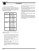
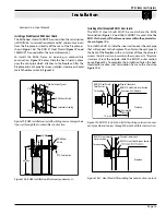
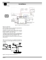
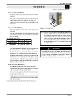
Section 3: Venting
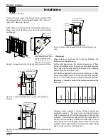
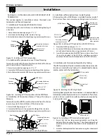
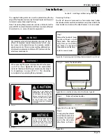
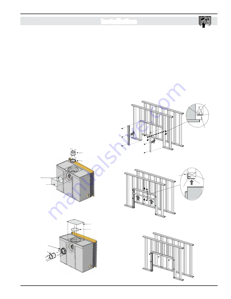
Figure 7.
Flue cover and collar removal, top vented fireplace.
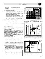
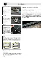
Figure 8.
Flue cover and collar installation, rear vented fireplace.
Section 3-1:
CONVERTING TO REAR VENT
Use the following instructions to convert an DV 42* for Rear
Vent use:
1. Remove the rear flue cover and gasket (5" and 8") on the
flue outlet, as shown in
Figure 7.
2. Next, remove the top flue collar's (5" and 8") on the flue
outlet, as shown in
Figure 7.
3. Install the (removed) rear flue cover and gasket material,
to the top vent outlet. Fasten the cover with included
hardware, as illustrated
Figure 8
.
4. Install the (5" and 8") collars to the rear vent outlet using
the included hardware, as illustrated
Figure 8
.
5” Inner Flue Collar
8” Outer Flue Collar
Flue Gasket
Flue Cover Plate
Flue Gasket
Flue Cover Plate
8” Outer Flue Collar
5” Inner Flue Collar
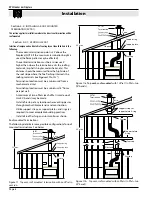
NOTES FOR PLANNING VENTING:
Venting can originate from the unit through the top or through
the rear. Venting can terminate through the roof or through
an exterior wall.
Refer to Appendix A - Termination Locations to ensure the
planned termination location is acceptable.
Once the termination location has been established, refer
to the appropriate section below for installation details. All
fireplaces shipped from the factory are
top vent.
See Section
3-1 for converting the unit from top vent to rear vent.
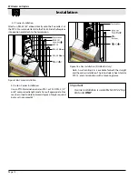
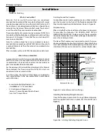
Figure 6.
Combustible Framing Side Heat Shield, (two pieces).
Framing Heat Shield
Included with the DV 42 Gas fireplace, is a framing heat shield
kit. This kit is fabricated from galvanized steel and arrives with
three pieces, as shown below. The shields protect all adjacent
combustible materials, mantels and mouldings from excessive
heat radiated by the fireplace.
NOTE: The shields must be installed as shown in
Figures 6
thru
6b.
Step 1. Fasten the two side shields first and ensure they are
fastened in place as shown. These are installed with the wide
flanges facing the center of the fireplace opening and the shallow
flange toward inside of room. These are also fastened with nails
or screws, flush with framing as shown in
Figure 6
and
Inset.
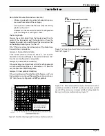
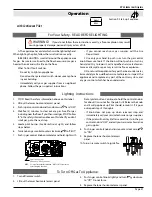
Figure 6a.
Combustible Framing Top Heat Shield, (one piece).
Figure 6b.
Combustible framing heat shield, completed.
Step 2. Next, fasten the top shield, with the wide flange face
up and the shallow flange toward inside of room,
Figure 6a
.
Step 3. Nail or screw the top shield in place flush with framing,
as shown in
Figure 6b.
fireplace
framing
fasteners,
3-per. side
Both Side
shields typical
flush with
framing
INSET
Section
fireplace
framing
Top shield
fasteners,
3-pcs.
INSET
Section
flush with
framing

