Page 11
DV52 Gas Fireplace
rev.101207
Installation
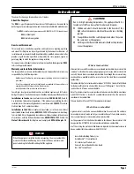
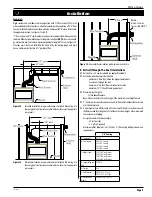
Important: Corner installation is available only for top vent
fireplaces.
Figure 20.
Corner installation.
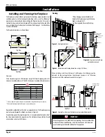
Figure 21.
Flex installation.
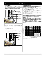
2. 45° Corner Installation.
Attach an PEL-90 (90° elbow) directly onto the flue collar, and attach it to the
PEL-45 (45° elbow). Cut the PXT-18 to suit and insert it into the PEL-45. Slide the
fireplace into position, and then connect it to the exterior termination.
3. Corner Installation — 45° or less.
Use a PTO-4 termination and an PFL-1 or PFL-2 (12" or 24" compressed length)
and a frame, if appropriate.
Flex may be turned to obtain desired degree of angle
required but must not exceed 45°.
IMPORTANT:
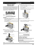
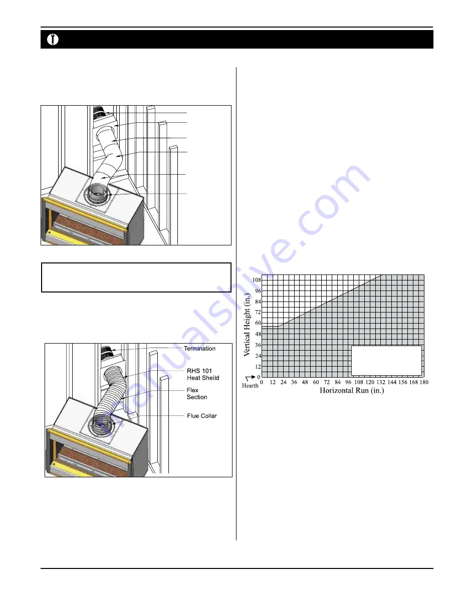
For both rear vent installations your vent run must fall within the
limits set by the Figure 22c vent graph.
Before you install any venting, you must determine whether the venting run will be
acceptable. Unacceptable venting can affect the fireplace's combustion.
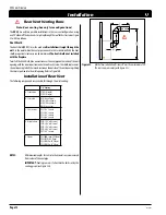
The Venting Graph
Measure the vertical height from the fireplace hearth to the center of the termination
and the horizontal run from the from the fireplace flue collar to the wall flange of the
termination. Plot on the Venting Graph (Figure 22c) with an 'X'.
If the 'X' falls on or above the top boundary of the shaded area, the installation is
acceptable.
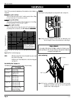
B. Multi-Elbow Installations
For more difficult installation situations, a rear-vented
DV 52
must be installed with
either one or two
90° elbows as described in a) or b), below:
a) One 90° elbow must be placed directly on the flue collar then place venting
vertically through the roof to the termination.
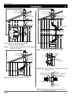
b) Two elbows as shown in Figure 23 using a
minimum
vertical lift of 50" (measured
from the hearth) as shown in Figure 23.
Figure 22c.
Multi-elbow venting graph.
Power Vent models, LDVPV47
EDVRSPV58, and EDVWSPV58
to be used within the shaded area
of graph. See index of this guide
for applicable product page.
Termination
Flue Collar
PEL-45 Elbow
PXT-18
RHS101
Heat Shield
PEL-90 Elbow


