Page 12
DV52 Gas Fireplace
rev.101207
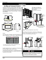
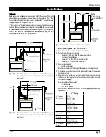
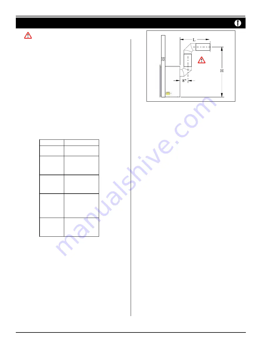
Figure 23.
Multi-elbow installation. Distance 'H' must be a minimum of 50".
The vent run must comply with Figure 22c.
NOTES:
All dimension lengths for vertical or horizontal runs are measured
from center of the vent pipe.
IMPORTANT:
Venting runs
must
fall within the limits set by the
venting graph (see Figure 22c).
Rear Vent Venting Runs
Note: Rear venting has only two configurations!
The
DV 52
has only two possible installations in the rear vent configuration; using
one 90° elbow off the back and straight up through the roof of the structure or Figure
23 with two elbows.
Heat Shield
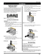
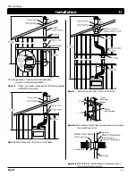
The heat shield (RHS101) must be used on
all installations straight through the
wall
, at the point where the vent pipe connects to the termination. With the heat
shield, proper vent clearances can be maintained.
The heat shield is not included
with the fireplace.
To install the heat shield, slide one section over the vent pipe on the inside of the wall
opening, with the circular portion
inside the wall cavity
. Screw the shield in place over
the wall opening. Install the second section on the outside of the wall opening sliding
the circular portion into the wall opening. Refer to Figure 16b.
Installation of Rear Vent
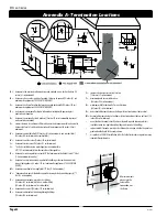
The following components are available for through-the-wall venting:
Installation
5"/8" Venting
A - Termination
PTO-4 (4" length)
PTO-4 (4" length)
B - Stucco Kits
MSR (Stucco Frame)
BSR-4 (4" Brick Frame)
BSR-6 (6" Brick Frame)
MOSR (Stucco Can)
C - Flex Sections
PFL-1 (12" Section)
PFL-2 (24" Section)
PFL-3 (36" Section)
PFL-4 (48" Section)
D - Rigid Sections
PEXT-1 (12" m/f Section)
PEXT-2 (24" m/f Section)
PEXT-3 (36" m/f Section)
PEXT-4 (48" m/f Section)
PXT-1 (20" Section)
E - Elbows
PEL-90MM (m/m 90° Elbow)
PEL-90FF (f/f 90° Elbow)
PEL-90FM (f/m 90° Elbow)
PEL-45FM (f/m 45° Elbow)


