Page 14
DV52 Gas Fireplace
rev.101207
Installation
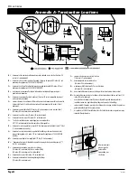
Surround Heat Shield
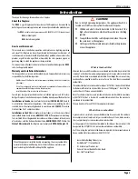
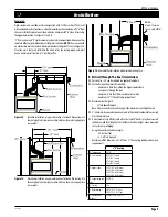
Included with the DV 52 Gas fireplace is a heat shield fabricated from galvanized steel.
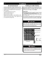
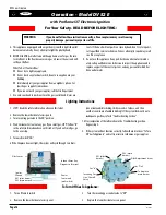
The kit comes with three (3) pieces as shown below. This shield is to protect all adjacent
combustible mantels and moldings from excessive heat radiated by the cabinet of the
fireplace. This shield must be installed as shown in
Figure 24a
.
1). Top shield fastened as shown. Wide flange face up, shallow flange toward inside
of room, nailed or screwed flush with framing.
2). Both side shields fastened as shown. Wide flanges face out, shallow flange toward
inside of room, nailed or screwed flush with framing.
Painting:
Special care is recommended by the Master Painters and Decorators Association, when
painting the fireplace surrounds, to select and apply a quality alkyd sealer prior to the
application of latex paints. This helps to prevent leaching of water from evaporation
which can cause a brownish staining to paint overcoats.
Mantels and Surrounds
NOTE:
National Canadian Gas Association mantel test requirements are for fire hazard
prevention to combustible materials.
New technology, to meet consumer and government demands for the wise use of
energy, has prompted us to manufacture many models of fireplaces which are hot
and energy efficient.
Please be aware that temperatures over the mantel will rise above normal room
temperature and walls above fireplace may be hot to touch.
Figure 24a.
Three piece combustible framing shield.
Fasteners
3-Per Shield
Framing
1/2
Side shield
Side shield
Top shield
Framing
1/2
Fasteners
3-Per Shield
4
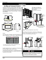
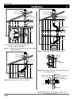
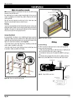
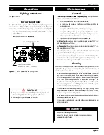
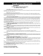
Figure 25.
Combustible surrounds.
Non-Combustible
Facing Material
Header
Drywall/Sheetrock
6”
3”
Wiring
DV 52
Gas Control Wiring
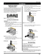
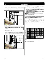
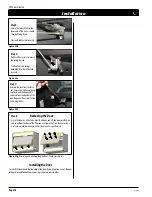
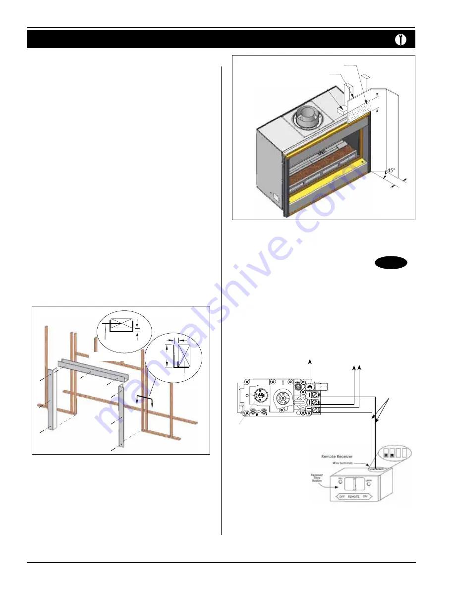
The DV 52 ships ready for manual operation. For remote control operation the
remote receiver must be connected.
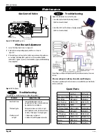
• Cut the white splice cap off of the end of the thermostat wire, strip the ends and
connect them to the remote receiver as shown in Figure 26.
• Install the four AA batteries and set the switch to the 'REMOTE', or center, posi-
tion.
See information sheet packaged with remote system for complete instructions.
Note:
Use only the included thermostat wire to connect the remote receiver.
Figure 26.
Wiring the
DV 52
remote receiver.
Thermostat Wire
(supplied)
to thermocouple
to thermopile


