background image

Page 5

DV52 Gas Fireplace

rev.101207

Installation

• 

Use only certified European Home vent components. Use of other parts will void the 
European Home warranty, and may impede the operation of the fireplace.

• 

All joints must be secured with a minimum of two screws per joint

• 

Vent terminations must not be recessed in walls or siding

• 

Horizontal runs must be supported by a minimum of two supports per horizontal run. A 
minimum of one screw on each side of support is also required

• 

Flex vent sections may be stretched up to 50% of their total length (e.g. a 24" section 
may be stretched to 36")

• 

Flex vent sections over 6 feet must fall within the limits set by the venting graph and must 
have a minimum vertical rise of 3 inches per foot of flex.

• 

Solid vent sections may be cut less than half way from the female end

• 

Venting components can be used in any combination of solid/rigid pipe or flex pipe and 
in any orientation, i.e. connectors can face in any direction.

Vent Terminations

Selecting A Termination Location

Choosing your vent termination location will help to determine whether you need to 
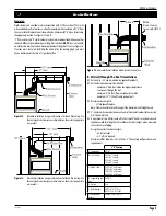
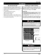
use a top vent or rear vent fireplace. Figure 6a, below, shows typical fireplace locations 
and the venting options they provide.      
For a more detailed diagram of allowed termination locations, see


Appendix A

.

Figure 6a.


Fireplace locations and vent terminations.

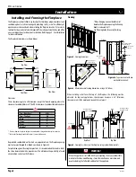
Installing The Gas Line

The gas line must be installed before finishing the DV 52 Gas Fireplace. Natural gas 
requires a minimum  inlet gas supply  pressure of 5.5" w.c. and a manifold pressure 
of 3.5" w.c. Propane gas requires a minimum inlet gas supply pressure of 11" w.c. and 
a manifold pressure of 10" w.c. Provision must also be made for a 1/8" NPT plugged 
tapping and be accessible for test gauge connection immediately upstream of the 
gas supply controls to the appliance. The fireplace gas connection and the main 
operating gas valve is located behind the removable trim at the bottom of the unit 
and need only be attached to the gas line  with an approved fitting, as required by 
the applicable installation codes.
• Only use gas shut-off valves approved for use by the state, province, region, or 
governing  body  in  which  the  appliance  is  being  installed  or  as  required  by  the 
applicable installation codes.
• Flexible gas connectors must not exceed 3 feet in length, unless it is allowable  within 
applicable installation codes.
The appliance and its individual shut-off valve must be disconnected from the gas 
supply piping system during any pressure testing of that system at test pressures in 
excess of 1/2 psig (3.5 kPa).

Note:

  After gas line is connected, 

each appliance connection

,

 valve and 

valve train

 must be checked while under normal operating pressure 

with either a liquid solution, or leak detection device, to locate any 
source of leak. Tighten any areas where bubbling appears or leak is 
detected until bubbling stops completely or leak is no longer detected. 

DO  NOT use a flame of any kind to test for leaks.

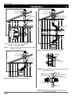
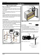
Figure 5a.  

Gas line access.

The appliance must be isolated from the gas supply piping system by closing its 
individual manual shut-off valve during any pressure testing of the gas supply piping 
system at test pressures equal to or less than 1/2 psig (3.5 kPa).

Vent  Installation

This section covers the installation of direct venting and terminations. 

Installation Requirements

• 

DV  52

  fireplaces  are  certified  for  use  with  European  Home  standard 

(5"/8")

 venting components.

• 

Minimum 

clearance to combustible construction around the vent pipe is 1" 

on 

all sides, except on horizontal venting where the 

top

 of the pipe must have a clearance 

of at least 2".

    Cautions: 

• 

Vent terminations can be very hot. If the termination is less than 
7 feet above a public walkway, it should be fitted with a certified 
European Home Heat Guard. (Part no. PTKOG).

• 

Do  not  obstruct,  or  attempt  to  conceal,  the  vent  termination.  

These actions will affect the operation of the fireplace, and may 

be hazardous.

• 

In heavy snow areas, take extra care to prevent snow buildup from 

obstructing the vent termination.

• 

Use European Home VSS Vinyl Heat Shield when using on applications 

with vinyl siding to guard against possible damage.

10" to center

Gas line access
7/8" diameter

2"

Summary of Contents for DV 52

Page 1: ...amage Refer to this manual For assistance or additional information consult a qualifiedinstaller serviceagencyorthe gassupplier Warning What to do if you smell gas Donottrytolightanyappliance Donottouchanyelectricalswitch do notuseanyphoneinyourbuilding Immediatelycallyourgassupplier fromaneighbor sphone Followthe gassupplier sinstructions Ifyoucannotreachyourgassupplier callthefiredepartment Inst...

Page 2: ...replace 13 Mantels and Surrounds 14 Table Of Contents Wiring 14 Removing and Installing the Door 15 Operation 17 Maintenance 19 Troubleshooting 20 Spare Parts 20 Warranty 21 Appendix A Termination Locations 22 B State of Massachusetts 23 Congratulations Congratulations on selecting a European Home gas fireplace an elegant and well designed gas fireplace built with you in mind The gas fireplace you...

Page 3: ...codes with the National Electrical Code ANSI NFPA 70 1987 Within the State of Massachusetts this fireplace must comply with NFPA 54 Chapter 10 CAUTION Due to its high operating temperatures the appliance should be located out of traffic and away from furniture and draperies Children and adults should be alerted to the hazards of the high surface temperature which could cause burns or clothing igni...

Page 4: ...commended that outer walls of the chase be insulated with a vapor barrier This will reduce the possibility of a cold air convection current on the fireplace Clearances These clearances apply to all dimensions except the framed opening where the clearancestocombustiblesare0 TheDV52clearancestocombustiblematerialsare Top Rear Vent N A Top Top Vent 24 Back 3 Sides 2 Floor 0 Mantle 4 TopView FrontView...

Page 5: ...e applicable installation codes Only use gas shut off valves approved for use by the state province region or governing body in which the appliance is being installed or as required by the applicable installation codes Flexiblegasconnectorsmustnotexceed3feetinlength unlessitisallowable within applicable installation codes The appliance and its individual shut off valve must be disconnected from th...

Page 6: ...that the two long mounting brackets are facing the bottom of the termination see inset This will provide more heat protection at the top of the termination where temperatures are highest 2 Attach to the faceplate of the termination using four sheet metal screws 3 If installing the termination over vinyl siding Use theVSSTermination Shield Installing Heat Guards overTerminations Installing The Stan...

Page 7: ...er Flue Cap 8 Outer Flue Cap Flue Gasket Flue Cover Plate 8 Outer Flue Collar 5 Inner Flue Collar 5 Inner Flue Collar 8 Outer Flue Collar Flue Gasket Flue Cover Plate 5 Inner ue Cap Fl Fl 8 Outer ue Cap Figure 7a Fluecapinstallation topventedDV52fireplace Figure 7b Fluecollarinstallation topventedDV52fireplace Figure 8a Fluecapinstallation rearventedDV52fireplace Figure 8b Fluecollarinstallation r...

Page 8: ...t run must fall withinthelimitssetbytheventinggraph 90 Elbow PEXT Section Termination If the X falls on or above the top boundary of the shaded area the installation is acceptable Example A Acceptable Installation Iftheverticaldimensionfromthehearthis84 andthehorizontalruntothewallflange of the vent termination is 36 the installation is acceptable Example B Acceptable Installation Iftheverticaldim...

Page 9: ...se B Vertical Through The Roof Installations Vertical rise 12 can be reduced on applicable models Vertical terminations must be installed minimum 2 two feet above the highest point where vent passes through the roof minimum 6 six feet from a mechanical air inlet minimum 18 11 2 feet from a parapet wall Maximum vent height is 32 feet above fireplace Note Flame characteristics will change if the max...

Page 10: ...th2offsets 1offset two90 bends Figure 16 Verticalventingwith1offset 1offset two90 bends PEXT PEXT PXT 10 Figure16a RHS8Installation Installbyslidingoverventpipewhereitpassesthrough thecombustibleconstruction Figure 16b RHS101Installation Installbyslidingoverventpipewhereitpasses throughthecombustibleconstruction Framing Drywall RHS101 Heat Shield Inner Section Vent from fireplace RHS101 Heat Shiel...

Page 11: ...ptable Unacceptable venting can affect the fireplace s combustion TheVenting Graph Measuretheverticalheightfromthefireplacehearthtothecenterofthetermination andthehorizontalrunfromthefromthefireplacefluecollartothewallflangeofthe termination Plot on theVenting Graph Figure 22c with an X If the X falls on or above the top boundary of the shaded area the installation is acceptable B Multi Elbow Inst...

Page 12: ...eld properventclearancescanbemaintained Theheatshieldisnotincluded with the fireplace Toinstalltheheatshield slideonesectionovertheventpipeontheinsideofthewall opening withthecircularportioninsidethewallcavity Screwtheshieldinplaceover thewallopening Installthesecondsectionontheoutsideofthewallopeningsliding the circular portion into the wall opening Refer to Figure 16b Installation of Rear Vent T...

Page 13: ...s Fireplace Facing When selecting the finish material for your fireplace it is important to remember that THE OPENING MUST NOT BE OBSTRUCTED IN ANY WAY Doing so restricts the air supply for the control compartments and heat exchanger as well as prevents access for servicing controls The face of the fireplace may be painted to match the room decor provided you use aheat resistantpaint Decorativefac...

Page 14: ...ention to combustible materials New technology to meet consumer and government demands for the wise use of energy has prompted us to manufacture many models of fireplaces which are hot and energy efficient Please be aware that temperatures over the mantel will rise above normal room temperature and walls above fireplace may be hot to touch Figure 24a Threepiececombustibleframingshield Fasteners 3 ...

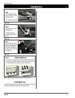
Page 15: ...gschematicforoptionalfans G L2 WH L1 BLK p g Quick Connect lu to motor 5 1 60 Supply G L1 L2 Removing and Installing the Door The doors are removed in a few simple steps Follow the steps below to remove the horizontal access panel unlatch the door buckles and remove the door Replace in reverse order Figure 28a Locatethedoorbuckles bothsidestypical Figure 28 Removingandinstallingthehorizontalaccess...

Page 16: ... spring tension Caution The latch springs back with force Hold the tool securely 4 Step7 Remove the tool from the latch slot Ensure the latches are hang ing freely and the hook end is released from the bottom of the door Repeat all four steps for the remaining latches Figure 28d Figure 28e Figure 28f Step8 Grasp the door on either side usually midway and lift the door carefully up andawayfromthefr...

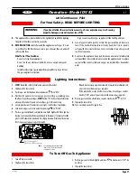
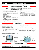
Page 17: ...ip down the lower trim 1 STOP Read the safety information above on this label 2 Flip down the lower trims 3 Push in gas control knob and turn clockwise to OFF 4 Wait five 5 minutes to clear out any gas Smell for gas including near thefloor Ifyouthensmellgas STOP Follow B inthesafetyinformation above on this label If you don t smell gas go to the next step 5 Locate pilot burner Seeillustrationatrig...

Page 18: ...ier s instructions If you cannot reach your gas supplier call the Fire Department C Use only your hand to push in or turn the gas control knob Never use 1 Turn off remote switch 2 Remove the lower horizontal access panel 3 Turn the incoming gas control valve to Off 4 Replace the lower horizontal access panel 1 STOP Read the safety information above on this label 2 Remove the lower horizontal acces...

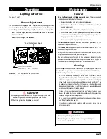
Page 19: ...gure 32 The front burners are not adjustable To raise the flame height turn the black knob located behind the lower trim counter clockwise To lower the flame height turn clockwise Figure 32 Hi Lo AdjustmentontheDV52gasvalve Cleaning When the fireplace is first activated there may be some smoking and a visible film may be left on the glass This is a normal condition and is the result of burning of ...

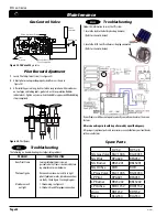
Page 20: ...t screw clockwise Pilot won t ignite Disconnect remote wires and try to light pilot If pilot now works remote connections are faulty Check Figure33 wiring diagram Main burner will 1 Check wiring see Figure 33 not light 2 Check wall switch for proper connection All service and repairs should be performed by a qualified agency All spare parts optional parts and accessories are available from your lo...

Page 21: ...ied by The Company 2 The European Home Gas Appliance must be subjected to normal use The Gas Appliances are designed to burn gas only Burning conventional fireplace fuels such as wood coal or any other solid fuel will cause damage to the Gas Appliance will produce excessive temperatures and will result in a fire hazard Limitations On Liability ItisexpresslyagreedandunderstoodthatTheCompanysoleobli...

Page 22: ...t 1 8m minimuminCanada L clearancetonon mechanicalairsupplyinlettobuildingorthecombustionairinlet toanyotherappliance 16inches 41cm minimumforappliances 100000BTU H 30kW M clearancetomechanicalairsupplyinlet 6feet 1 8m minimum N clearanceabovepavedsidewalkorapaveddrivewaylocatedonpublicproperty 7 feet 2 1m minimum P clearanceunderveranda porch deck orbalcony 16inches 41cm minimum tonon combustible...

Page 23: ...line with the exhaust vent terminal for the horizontally vented gas fueled heating appliance or equipment The sign shall read in print size no less than one half 1 2 inch in size GASVENT DIRECTLY BELOW KEEP CLEAR OF ALL OBSTRUCTIONS 4 INSPECTION The state or local gas inspector of the side wall horizontally vented gas fueled equipment shall not approve the installation unless upon inspection the i...

Page 24: ...EUROPEAN HOME a division of Europa Ja Inc 376 Washington St Suite 203 Malden MA 02148 tel 781 324 8383 fax 781 324 8384 www europeanhome com ...

Reviews: